
Apparatus and method for sedimentation field-flow fractionation

a technology of sedimentation field and apparatus, applied in the field of fieldflow fractionation, can solve the problems of sample damage, leakage, contamination, and limited use of sdfff, and achieve the effects of enhancing the selectivity of the apparatus, significantly enhancing separation resolution, and enhancing precision

Active Publication Date: 2013-06-11
SENFTLEBER FRED C
View PDF12 Cites 0 Cited by
  • Summary
  • Abstract
  • Description
  • Claims
  • Application Information

AI Technical Summary

Benefits of technology

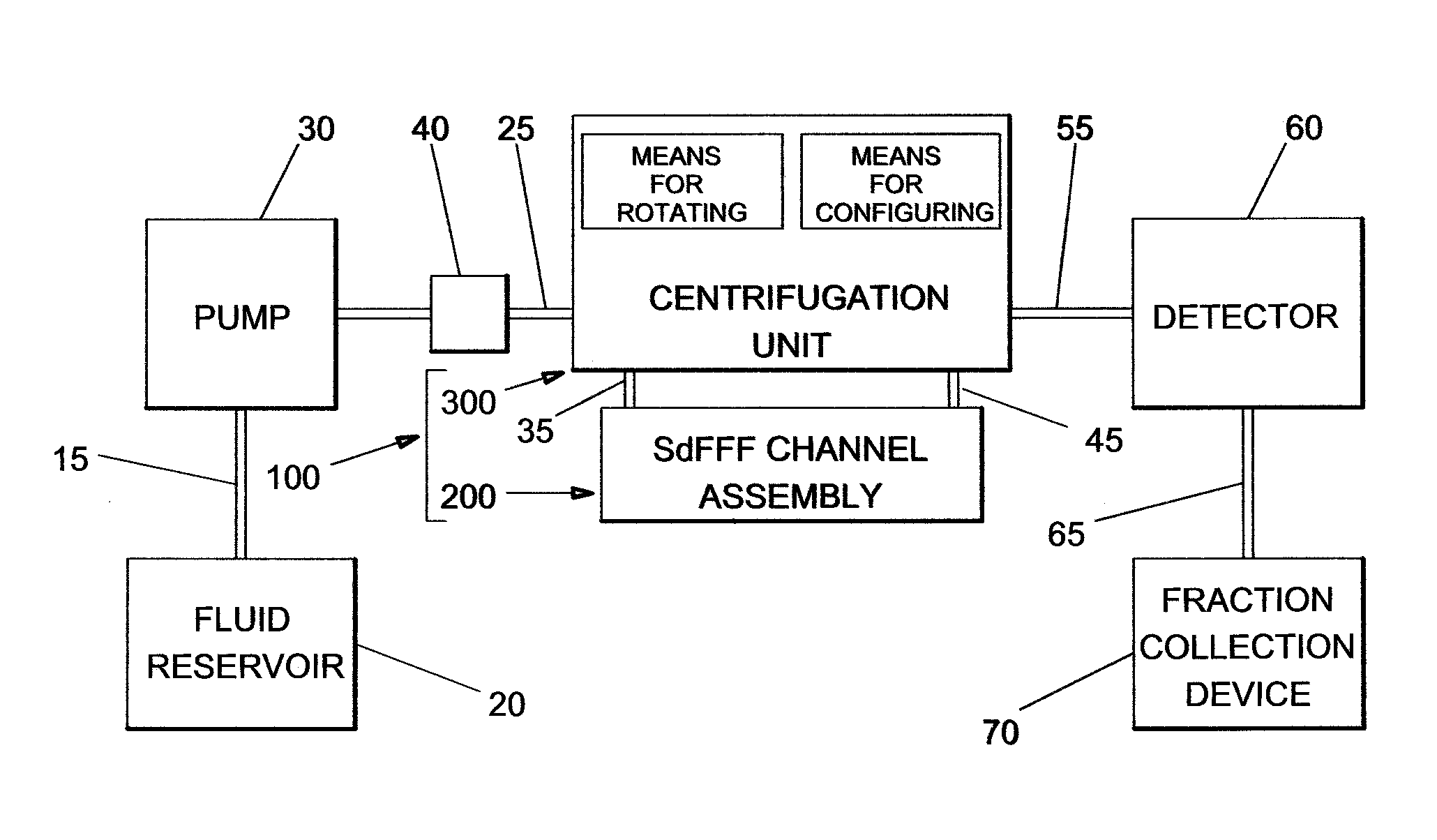
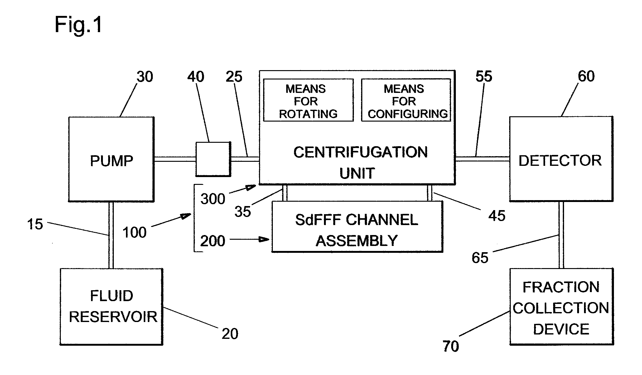
[0020]Alternative embodiments of the present invention integrate means to create secondary forces that enable other modes of field-flow fractionation (FFF) to couple with the sedimentation forces to further enhance the selectivity of the apparatus to separate and isolate specific fractions of particles from complex sample mixtures. The secondary force can also be used to hold and concentrate the sample components at the entrance to the separation channel as part of what is called a “relaxation” procedure. This aggregates sample particles initially to a smaller volume in the slower moving fluid and can result in significantly greater separation resolution. In electrical field-flow fractionation (abbreviated as EFFF), for example, particles are exposed to an electrophoretic force that enables discrimination on the bases of size and charge. Other embodiments exploit the dielectrophoretic (DEP-FFF) and magnetic (MgFFF) properties of the particles to be separated. In some modes of FFF, the force is developed by imposing a gradient across the channel as in thermal (ThFFF) or concentration (CgFFF) field-flow fractionation or by directing a second independent flow stream across the channel as in flow (FIFFF) and asymmetric flow (AFFFF or AF4) field-flow fractionation. The secondary force can be oriented to align, oppose, or operate at some intermediate angle with respect to the sedimentation force. At an angle of 90°, the two fields create a two-dimensional distribution of sample particles. Additional fluid, electrical, optical, and mechanical communication means to produce and / or support the secondary force are provided using the looping-tube twist-compensating transfer system operating inside the centrifugation unit.
[0021]Other embodiments of the present invention employ a plurality of channels for parallel or serial analysis of sample particles. Channels may be arranged side-by-side, end-to-end, or stacked and may be designed to function independently or connected together sequentially or in an array to enable coupled operation. Many of the embodiments employ multiple inlets and / or outlets on the channels to accommodate the additional features and means for fluid communications. Embodiments incorporating a plurality of channels enable simultaneous analysis of multiple samples, enhanced precision through easy replication, and increased sample-loading capacity for preparative-scale separations, all while providing almost infinite flexibility in selecting and combining separation parameters.

Problems solved by technology

The difficulty generally arises in that a means must be provided to maintain fluid communication between the rotating channel and stationary components within the instrument.
Although simple in concept, it is the rotating seals that create most of the problems and limitations in the use of SdFFF.
The principal troubles come from leakage, contamination, and sample damage, particularly when the seal is operated at high rotational speeds.
Leakage, which is typically the greatest problem with rotating seals, is generally due to wear at the contact interface as the rotating members slide against one another.
Additional leakage is also caused by misalignment and separation between the cylindrical members brought about by vibration as the members rotate.
Heat due to friction can further exacerbate the wear and can ultimately limit the rotational speed at which the seal can be operated.
Heat and shear forces at the interface can also damage fragile sample particles.
In addition, debris from wear can restrict flow and contaminate fluid as it passes through the seal interface.
Although effective to varying degrees, most of the improvements add complexity and additional cost to the seal design while still not totally eliminating the problems.
Another difficulty created by the use of rotating seals is that the seals limit the number of rotating lines of communication that can be established with the SdFFF channel and thus severely restrict the ways the SdFFF apparatus can be configured and operated.
As evidenced by the absences of examples in the literature, even the use of a concentric double-bore rotating seal as described in U.S. Pat. No. 4,502,699 provides little improvement over the use of the single-bore models in the development of higher-order techniques in SdFFF.
The rotating-seal type coupling devices currently employed in SdFFF are a major source of problems in both reliability and maintenance.
In addition, the seals dramatically limit the ability to expand the instrumentation to permit more advanced, higher-order separation capabilities.

Method used


Image

  • Apparatus and method for sedimentation field-flow fractionation
  • Apparatus and method for sedimentation field-flow fractionation
  • Apparatus and method for sedimentation field-flow fractionation

Examples


Embodiment Construction

[0062]The present invention will now be described more fully hereinafter with reference to the accompanying drawings, in which a preferred embodiment of the invention is shown. This invention may, however, be embodied in many different forms and should not be construed as limited to the embodiment set forth herein. Rather, this embodiment is provided so that this application will be thorough and complete, and will fully convey the true scope of the invention to those skilled in the art. Like numbers refer to like elements throughout the figures.

[0063]The illustrations of the embodiments described herein are intended to provide a general understanding of the structure of the various embodiments. The illustrations are not intended to serve as a complete description of all of the elements and features of apparatus and systems that utilize the structures or methods described herein. Many other embodiments may be apparent to those of skill in the art upon reviewing the disclosure. Other ...


PUM


Abstract

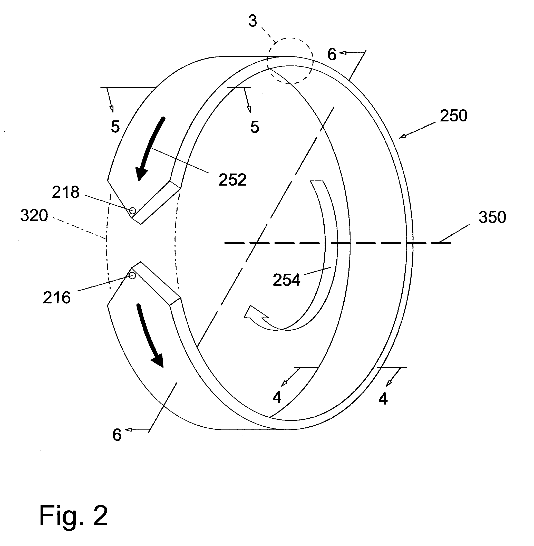
Apparatuses and methods are described for the discrimination of particles using sedimentation field-flow fractionation operating without the use of rotating seals. Multiple lines of fluid and electrical communication are provided through a centrifugation unit comprising a fishhook-shaped umbilical conduit traveling from a stationary frame through a rotating guide frame to the separation channel. Twisting and tangling of the umbilical conduit enclosed communication lines are prevented by rotating the guide frame and separation channel in the same direction about an axis at an angular velocity ratio of 1:2. The design eliminates maintenance problems associated with rotating seals, simplifies channel installation and adjustment, and enables the use of multiple channels and the simultaneous application of multiple modes of field-flow fractionation either in concert or in a two-dimensional format. The design also enables the injector and / or detector to be mounted contiguously with the separation channel on the centrifugal rotor.

Description

CROSS REFERENCE TO RELATED APPLICATIONS[0001]Not Applicable.STATEMENT REGARDING FEDERALLY SPONSORED RESEARCH OR DEVELOPMENT[0002]Not Applicable.REFERENCE TO A MICROFICHE APPENDIX[0003]Not Applicable.BACKGROUND OF THE INVENTION[0004]1. Technical Field[0005]This application relates generally to field-flow fractionation. More specifically, the application provides apparatuses and methods for the discrimination of particles using sedimentation field-flow fractionation operating without the use of rotating-seal type coupling devices.[0006]2. Prior Art[0007]Field-flow fractionation (FFF) is a single-phase elution-based particle separation and characterization technique developed in the late 1960's by J. C. Giddings at the University of Utah. The first patents for the technique were issued to John C. Giddings in Jun. 17, 1969 (U.S. Pat. No. 3,449,938) and to Edward M Purcell and Howard C. Berg in Aug. 11, 1970 (U.S. Pat. No. 3,523,610). To effect a separation using FFF, the sample particle...

Claims


Application Information

Patent Timeline
Patent Type & Authority Patents(United States)
IPC IPC(8): B03C1/30
CPCB03C1/288B03C1/30B03C5/026B04B5/0442G01N30/0005G01N2030/002B04B2005/045B03C2201/18
Inventor SENFTLEBER, FRED C.
Owner SENFTLEBER FRED C
Learn More