System and method for replicating orthopaedic implant orientation

a technology of orthopaedic implants and articulating heads, which is applied in the field of prosthetic devices, can solve the problems of humeral prosthesis often only achieving the best-fit relationship, more wear and tear on joints, and increased risk of serious joint injuries

Active Publication Date: 2013-06-11
DEPUY SYNTHES PROD INC
View PDF81 Cites 9 Cited by
  • Summary
  • Abstract
  • Description
  • Claims
  • Application Information

AI Technical Summary

Problems solved by technology

Longer life spans mean that the joints endure more wear and tear.
More sports activities mean greater likelihood of serious joint injuries.
Absent an infinite variety of pre-determined head geometries, the resulting humeral prosthesis can often only achieve a best-fit relationship to the glenoid component of the shoulder joint.
Even with respect to these two divergent manners of surgical strategy, a common problem in shoulder surgery is matching the humeral resection angle across the articular margin to the predetermined angle designed into the prosthesis.
This strategy does not allow the surgeon to intraoperatively match the implant to the patient's biomechanics after the prosthesis has been trialed, much less implanted.
This system, however, has two primary weaknesses.
First, the use of modular blocks obviously forces the design to only allow angular adjustments in finite increments.
Second, the need to adjust the angle through modular blocks forces the surgeon to remove the stem, change out a component, and reset the stem.
The locking mechanism, however, is sub-optimal since it requires the turning of a locking screw that has its head facing lateral and inferior, for which there is no access once the stem has been cemented.
Lastly, the protrusion on the humeral stem even when the humeral head is not in place limits the surgeon's access to the glenoid in preparation for a glenoid replacement.
This method produces galling of the broach which can significantly limit the useful life of the broach.
Moreover, the impaction step frequently causes the trial broach to sink further into the IM canal.
In addition, discrepancies between the amount of impaction of the trial element vis-à-vis the final implant element results in an unknown offset of this center of rotation, which ultimately leads to a poor anatomic fit and improper alignment of the humeral head prosthesis.

Method used


Image

  • System and method for replicating orthopaedic implant orientation
  • System and method for replicating orthopaedic implant orientation
  • System and method for replicating orthopaedic implant orientation

Examples


Embodiment Construction

[0041]While the invention is susceptible to various modifications and alternative forms, specific embodiments thereof have been shown by way of example in the drawings and will herein be described in detail. It should be understood, however, that there is no intent to limit the invention to the particular forms disclosed, but on the contrary, the intention is to cover all modifications, equivalents, and alternatives falling within the spirit and scope of the invention.

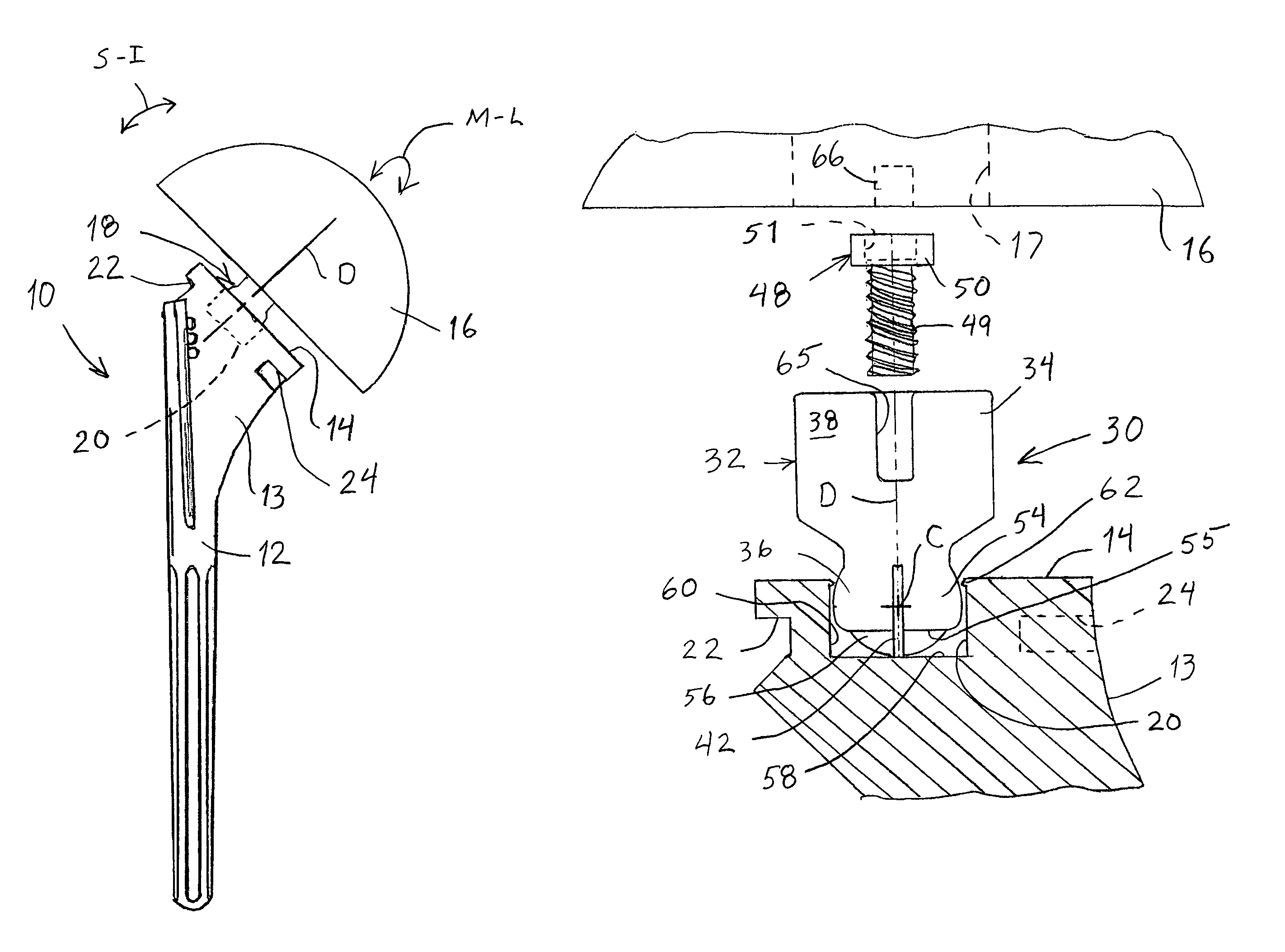
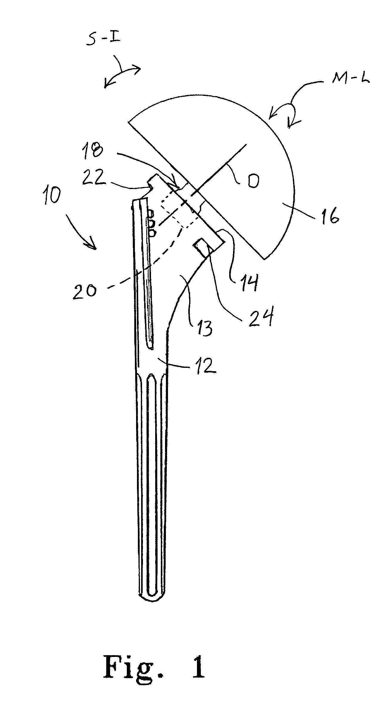
[0042]For purposes of illustration, the preferred embodiment of the invention is described in connection with a shoulder prosthesis, and particularly the humeral component of the prosthesis. However, the inventive concepts disclosed herein can be used at other joints or bone interfaces of the body. The common feature among these alternative uses of the invention is that they include components that can assume a range of angular orientations relative to each other—angular orientations that must be duplicated from a tria...


PUM


Abstract

A trial implant system includes a stem component and an articulating component forming part of a joint of a patient. A trial mounting assembly mounts the articulating component to the stem component at variable relative angular positions. The trial mounting assembly includes an expandable ball portion and an expansion element configured to expand the ball portion upon rotation of the expansion element. In an expanded state, the ball portion contacts a cavity within the stem at three points of contact to fix the center of rotation of the ball portion at a pre-determined location within the stem. The stem cavity defines an inwardly projecting circumferential lip that bears against ball portion as it expands to ensure the three-point contact.

Description

BACKGROUND OF THE INVENTION[0001]1. Field of the Invention[0002]The present invention relates to prosthetic devices and, more specifically, to a system and method for replication of angular position of an articulating head of a prosthesis. The invention has particular application to the humeral component of a shoulder prosthesis.[0003]2. Background Information[0004]Repair and replacement of human joints, such as the knee, shoulder, elbow and hip, has become a more and more frequent medical treatment. Longer life spans mean that the joints endure more wear and tear. More sports activities mean greater likelihood of serious joint injuries. Treatment of injuries, wear and disease in human joints has progressed from the use of orthotics to mask the problem, to fusion of the joint, to the use of prostheses to replace the damaged joint component(s).[0005]As the success rate for total or partial joint replacements has increased, so too has the need for modularity and universality in the jo...

Claims


Application Information

Patent Timeline
Patent Type & Authority Patents(United States)
IPC IPC(8): A61F2/40
CPCA61F2/4014A61F2/4684A61F2002/30484A61F2002/4668A61F2220/0025
Inventor BISS, MATTHEWLONG, JACKFRAZEE, EDMUND
Owner DEPUY SYNTHES PROD INC
Why Eureka
Try Eureka