Specimen collection container assembly

a technology for specimen collection and container assembly, which is applied in the field of specimen collection container assembly, can solve the problems of many conventional capillary specimen collection containers that are not compatible with automated front end processes used to prepare specimens, many conventional capillary specimen collection containers that are not dimensioned to accommodate, and many conventional capillary specimen collection containers that are not compatible with automated analysis procedures and other issues, to achieve the effect of maintaining the sterility of the interior and improving the sealing mechanism

Active Publication Date: 2013-06-11
BECTON DICKINSON & CO
View PDF176 Cites 28 Cited by
  • Summary
  • Abstract
  • Description
  • Claims
  • Application Information

AI Technical Summary

Benefits of technology

[0007]Accordingly, a need exists for a capillary specimen collection container having improved sealing mechanisms for maintaining the sterility of the interior of the specimen collection container and / or the interior and exterior of the scoop or funnel. It is also desirable to maintain the purity of the specimen deposited within the specimen collection container prior to performance of a testing procedure.

Problems solved by technology

As such, many conventional capillary specimen collection containers are not compatible with automated front end processes used to prepare a specimen for proper analysis, such as sorting specimen collection containers by type and / or contents, accessorizing specimen collection containers superficially or with additives specific to the contents of the specimen collection container, centrifugation, vision based specimen quality analysis, serum level analysis, decapping, aliquoting, and automated labeling of secondary tubes.
In addition, many conventional capillary specimen collection containers are not compatible with automated analyzing procedures and are not dimensioned to accommodate automated diagnostic and / or analyzing probes or other specimen extraction equipment.
Further, many conventional capillary specimen collection containers are not compatible with certain automated back end processes employed after a specimen is analyzed, such as resealing, storage, and retrieval.

Method used


Image

  • Specimen collection container assembly
  • Specimen collection container assembly
  • Specimen collection container assembly

Examples


Embodiment Construction

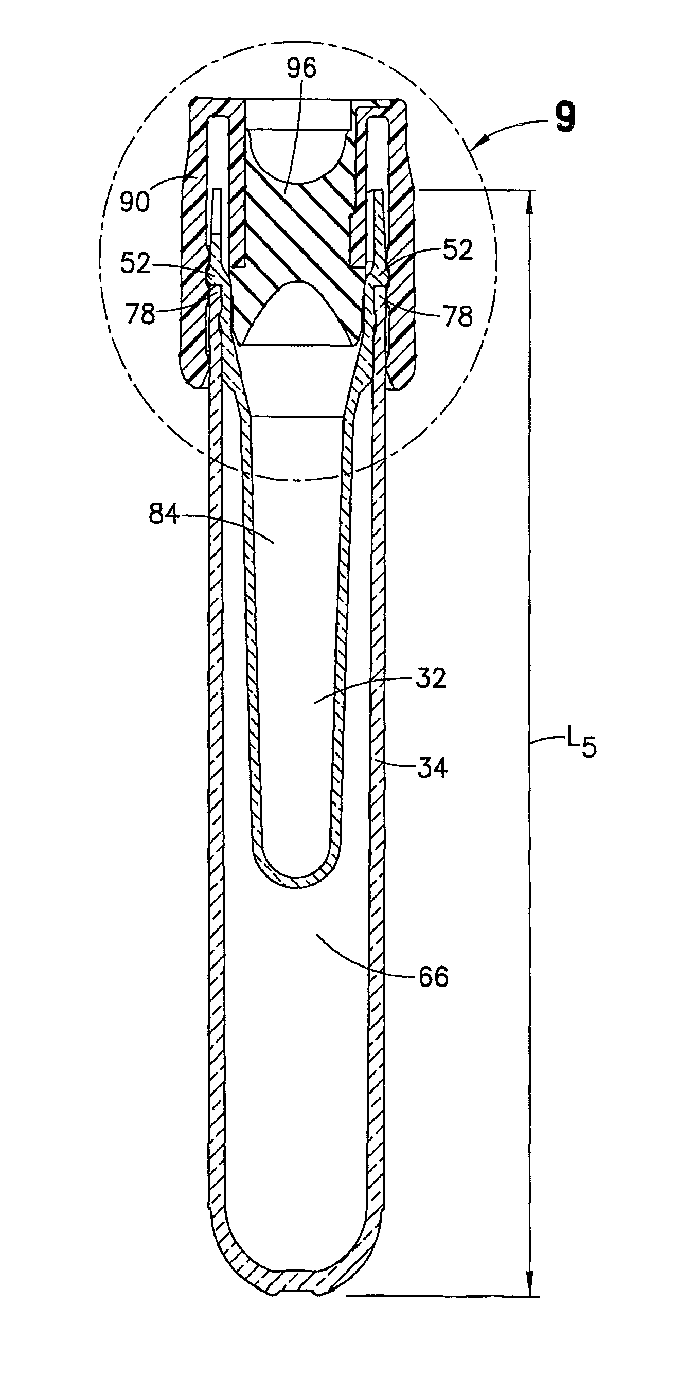
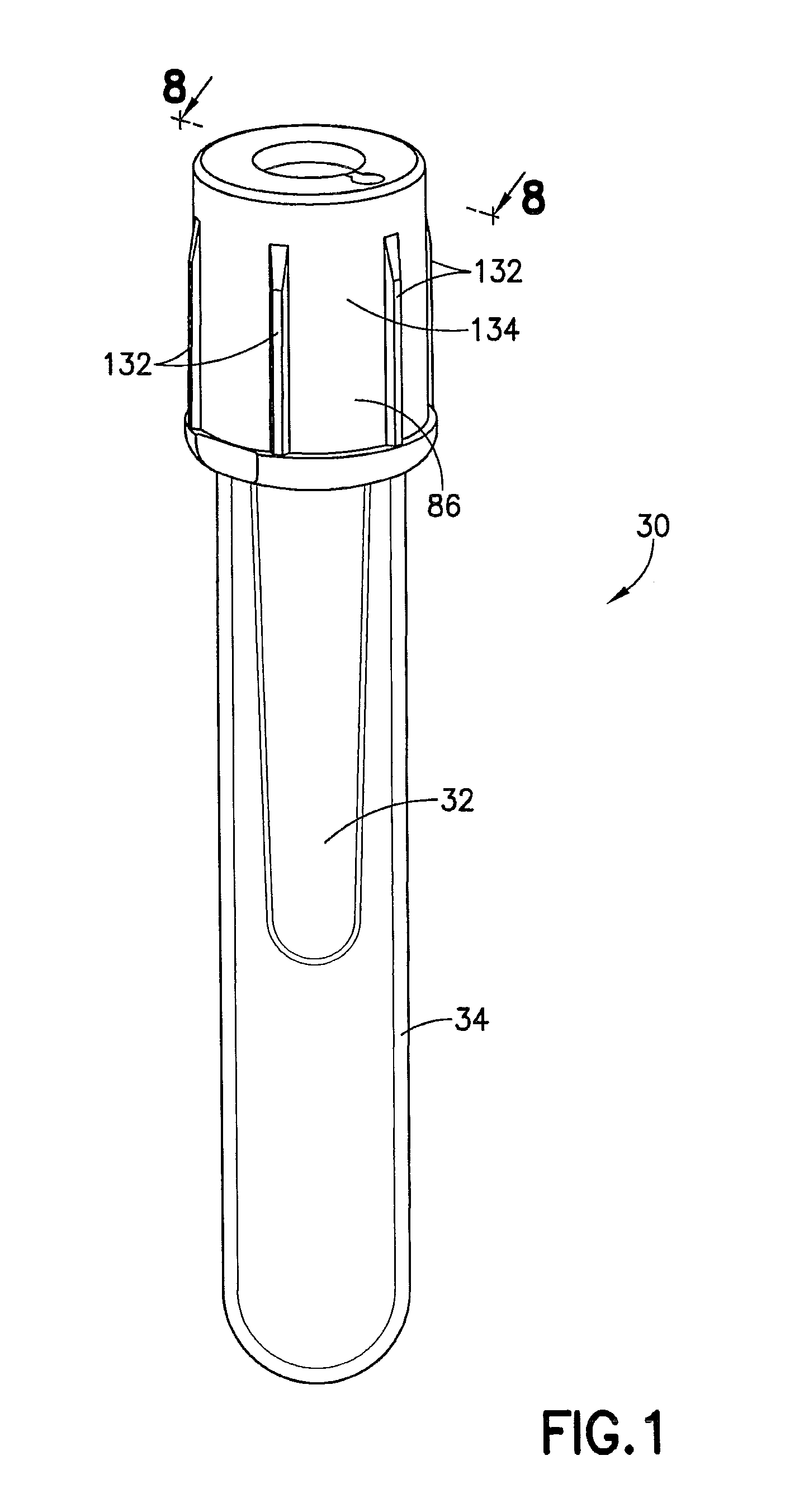
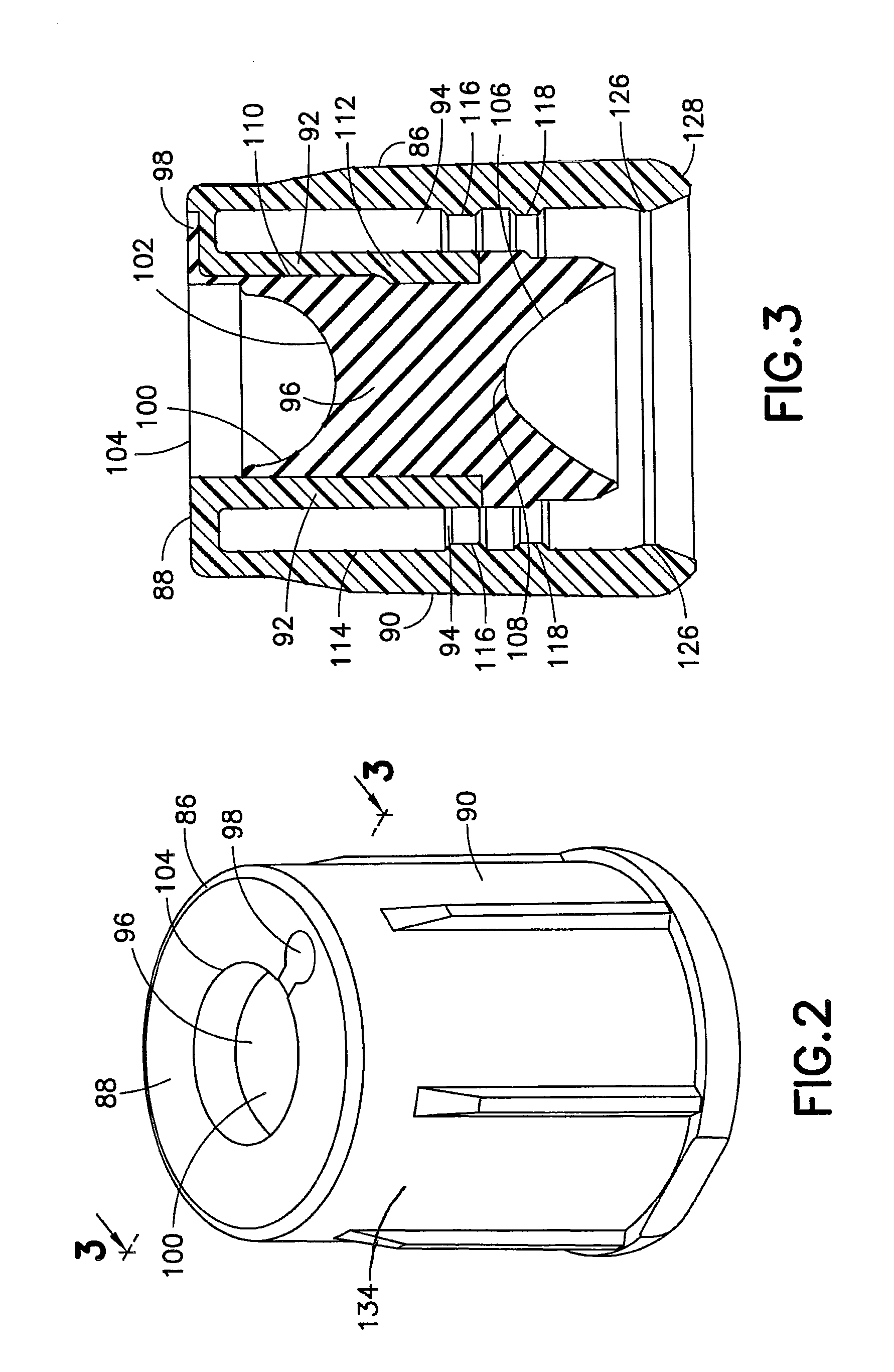
[0038]As shown in FIG. 1, a specimen collection container assembly 30, such as a biological fluid collection container, includes an inner tube 32, an outer tube 34, and a specimen cap 86. The inner tube 32, as shown in FIGS. 4-5, is used for the collection and containment of a specimen, such as capillary blood or other bodily fluid, for subsequent testing procedures and diagnostic analysis. The outer tube 34, as shown in FIGS. 6-7, acts primarily as a carrier for the inner tube 32, providing additional protection for the contents of the inner tube 32 as well as providing external dimensions that are compatible with standard automated clinical laboratory processes, such as Clinical Laboratory Automation. The specimen cap 86, as shown in FIGS. 2-3, provides a means for a user to access the inner tube 32 to obtain the specimen deposited therein, and also provides a leak proof seal with the inner tube 32 upon replacement of the specimen cap 86, as will be discussed herein.

[0039]Referrin...


PUM


Abstract

A specimen collection container includes inner and outer tubes. The inner tube includes a bottom end, a top end, and a sidewall extending therebetween defining an interior. The sidewall includes an inner surface and an outer surface having at least one annular protrusion extending therefrom. The inner tube includes at least one funnel portion adjacent the top end for directing a specimen into the inner tube interior, and an annular ring disposed about a portion of the outer surface of the sidewall adjacent the top end. The outer tube includes a bottom end, a top end, and a sidewall extending therebetween, the sidewall having an outer surface and an inner surface defining an annular recess adapted to receive a portion of the annular protrusion therein. The inner tube is disposed within the outer tube and a portion of the top end of the outer tube abuts the annular ring.

Description

CROSS-REFERENCE TO RELATED APPLICATION[0001]This application claims priority to U.S. Provisional Patent Application No. 61 / 419,587, filed Dec. 3, 2010, entitled “Specimen Collection Container Assembly”, the entire disclosure of which is herein incorporated by reference.BACKGROUND OF THE INVENTION[0002]1. Field of the Invention[0003]The present invention relates to a specimen collection container assembly and, more particularly, to a specimen collection container assembly having improved sterility and suitable for use with automated clinical processes.[0004]2. Description of Related Art[0005]Medical capillary collection containers have historically been used for the collection of specimens, such as blood and other bodily fluids, for the purpose of performing diagnostic tests. Many of these capillary collection containers include a scoop or funnel for directing a specimen into the collection container. In most cases, capillary specimen collection containers are not sterile. In order t...

Claims


Application Information

Patent Timeline
Patent Type & Authority Patents(United States)
IPC IPC(8): B01L3/14B65D25/00A61B10/00
CPCB01L3/5082B01L3/50825B01L2200/026B01L2200/082B01L2300/123B01L2300/042B01L2300/044B01L2300/0609B01L2300/0832B01L2200/141B01L2200/0684B01L2300/0858B01L2200/025
Inventor BARTFELD, BENJAMIN R.ELLIS, ROBERT G.GOLABEK, JR., ROBERT S.DUBROWNY, NANCYPARMAR, GIRISHHOLMES, PAULBLEKHER, ALEXDELK, MICHAEL
Owner BECTON DICKINSON & CO
Why Eureka
Try Eureka