Fuel cell system

a fuel cell and system technology, applied in the field of fuel cell systems, can solve the problems of inability to carry out output control based on required electric power, inability to supply electric power in excess or deficiency of electric power, and inability to meet the requirements of electric power supply, so as to increase the voltage value of the operating point

Active Publication Date: 2013-06-11
TOYOTA JIDOSHA KK
View PDF11 Cites 3 Cited by
  • Summary
  • Abstract
  • Description
  • Claims
  • Application Information

AI Technical Summary

Benefits of technology

[0012]With this arrangement, surplus electric power exceeding the electric power generation command value can be stored into the capacitive component of the fuel cell when the electric power generation command value suddenly reduces during the low-efficiency operation, thus making it possible to restrain the supply of surplus electric power to an external load from the fuel cell.
[0015]A capacitive component of a fuel cell is known to deteriorate with the elapse of time by catalytic oxidation or the like after use over a prolonged time. Surplus electric power can be accurately stored into the capacitive component by correcting the map data indicating capacitance values relative to voltages of the capacitive component on the basis of actually measured values of the capacitive component.
[0016]The fuel cell system in accordance with the present invention may further comprise an electric power generation command device which gently reduces an electric power generation command value such that a difference between the amount of generated power of the fuel cell and the electric power generation command value is controlled in the case where an operating load on the fuel cell is suddenly decreased in the midst of the low-efficiency operation.
[0017]Surplus electric power can be minimized and the difference between the amount of generated power supplied to an external load of the fuel cell and an electric power generation command value can be reduced by gently decreasing the electric power generation command value such that the difference between the amount of generated power of the fuel cell and an electric power generation command value is controlled.
[0020]Changing the low-efficiency operation over to the normal operation requires the operating point of the fuel cell be moved to an operating point determined by the current-to-voltage characteristic curve from the low-efficiency operation range (the voltage value of the operating point be increased). At this time, forcibly generating surplus electric power by oversupplying the reactant gas to the fuel cell and increasing the output voltage of the fuel cell to store the surplus electric power into the capacitive component make it possible to switch the operation mode from the low-efficiency operation to the normal operation without causing a change in the electric power supplied to an external load of the fuel cell.

Problems solved by technology

Here, the reason for fixing the output voltage of the fuel cell to a given voltage value is because, in the case where operation control is conducted with the output voltage of the fuel cell set to a voltage that is lower than a voltage based on the I-V characteristic thereof to lower the electric power generation efficiency during a warm-up operation, a change (an increase or decrease) in the output voltage of the fuel cell would inconveniently cause electric power to be stored or released in or from a capacitive component, which is parasitically formed in the fuel cell, resulting in an excess or deficiency of electric power supplied from the fuel cell to an external load (a traction motor, a vehicle-mounted auxiliary device, or the like).
Meanwhile, according to the technique disclosed in Japanese Patent Application Laid-Open No. 2002-313388, the output of the fuel cell is undesirably reduced in compensation for lowering the electric power generation efficiency of the fuel cell at the time of the warm-up operation, making it impossible to carry out output control based on required electric power.
However, in some fuel cell hybrid vehicles using fuel cell systems as the vehicle-mounted electric power sources thereof, oxidizing gases are supplied to fuel cells by air compressors.
However, many air compressors are not provided with speed reducers, such as brakes, thus exhibiting poor responsiveness to an abrupt decrease in the opening degree of the accelerator pedal.
Accordingly, even if the opening degree of the accelerator pedal is suddenly decreased during the low-efficiency operation while the vehicle is traveling, the flow rate of the oxidizing gas to the fuel cell cannot be suddenly decreased, inconveniently resulting in the generation of surplus electric power exceeding an electric power generation command value.
Although the surplus electric power is stored into a battery, the battery may be overcharged in the case where the charge capability of the battery has been deteriorated in a low-temperature environment.

Method used


Image

  • Fuel cell system
  • Fuel cell system
  • Fuel cell system

Examples


Embodiment Construction

[0032]The following will describe an embodiment in accordance with the present invention with reference to the accompanying drawings.

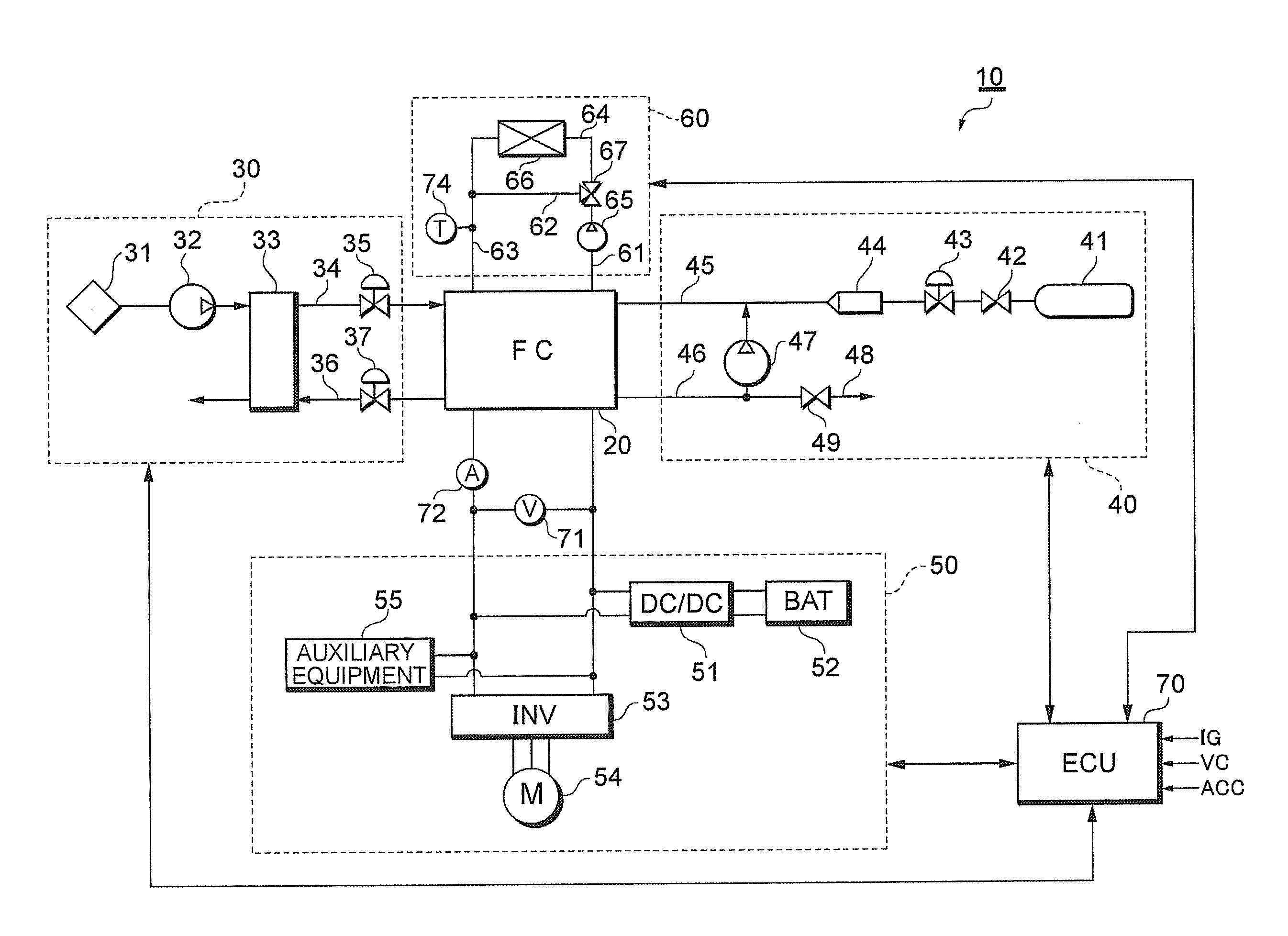
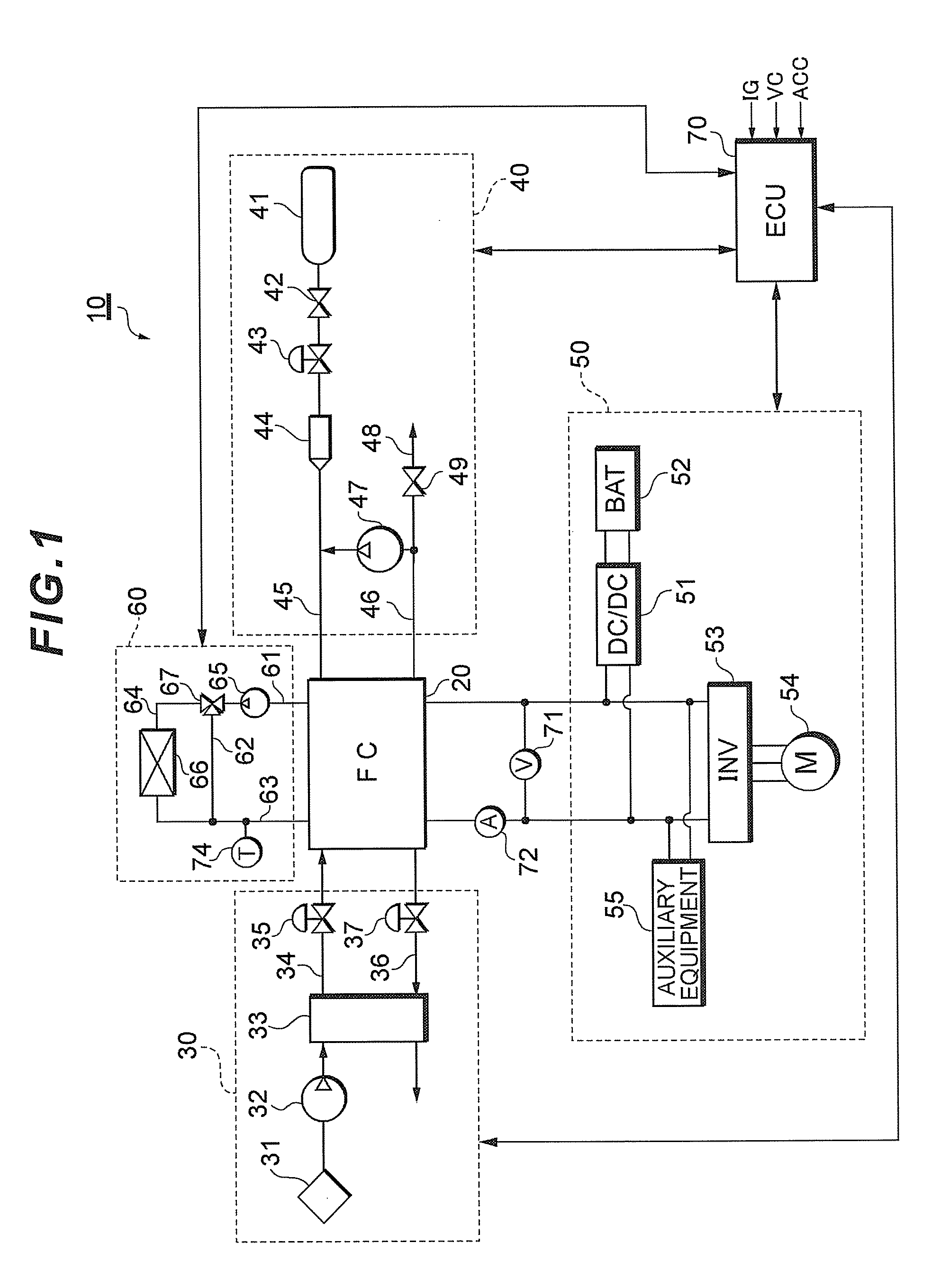
[0033]FIG. 1 is a system configuration of a fuel cell system 10 according to the present embodiment.

[0034]The fuel cell system 10 functions as a vehicle-mounted electric power source system installed in a fuel cell hybrid vehicle, and includes a fuel cell stack 20 which receives the supply of a reactant gas (a fuel gas and an oxidizing gas) to generate electric power, an oxidizing gas supply system 30 for supplying air as the oxidizing gas to the fuel cell stack 20, a fuel gas supply system 40 for supplying a hydrogen gas as the fuel gas to the fuel cell stack 20, an electric power system 50 for controlling the charge / discharge of electric power, a cooling system 60 for cooling the fuel cell stack 20, and a controller (ECU) 70 which controls the entire system.

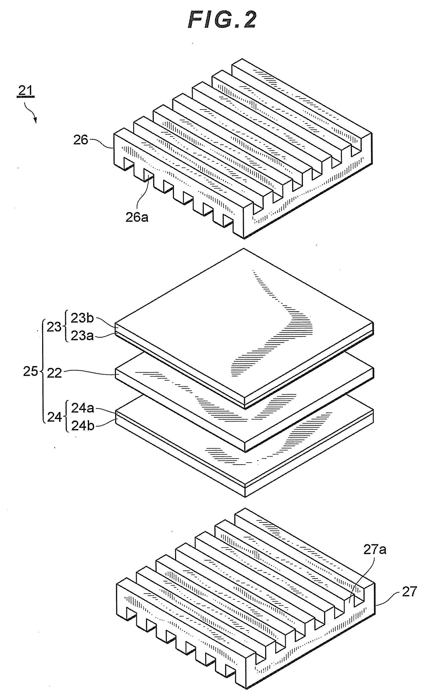
[0035]The fuel cell stack 20 is a solid polymer electrolytic cell stack composed of a pluralit...


PUM

PropertyMeasurementUnit
temperatureaaaaaaaaaa
pressureaaaaaaaaaa
pressureaaaaaaaaaa

Abstract

A fuel cell system increases an output voltage of a fuel cell if an electric power generation command value Pref for the fuel cell abruptly reduces while the fuel cell is being warmed up at a low-efficiency operation, which has lower electric power generation efficiency than that of a normal operation. Thus, the surplus electric power Ws corresponding to the difference between an electric power generation amount Pmes of the fuel cell and the electric power generation command value Pref is stored into a capacitive component of the fuel cell, thereby matching the electric power supplied to an external load of the fuel cell (Pmes-Ws) with the electric power generation command value Pref. This makes it possible to conduct control not to supply the surplus electric power to the external load when the electric power required from the fuel cell suddenly reduces during the low-efficiency operation.

Description

[0001]This is a 371 national phase application of PCT / JP2008 / 065478 filed 22 Aug. 2008, which claims priority to Japanese Patent Application No. 2007-221336 filed 28 Aug. 2007, the contents of which are incorporated herein by reference.TECHNICAL FIELD[0002]The present invention relates to a fuel cell system adapted to warm up a fuel cell by low-efficiency operation.BACKGROUND ART[0003]A fuel cell is an electric power generating system which oxidizes a fuel by an electrochemical process to directly convert the energy emitted due to an oxidation reaction into electrical energy, and which has a stack structure constituted of a plurality of layered membrane electrode assemblies formed by sandwiching both side surfaces of an electrolyte membrane for selectively transporting hydrogen ions by a pair of electrodes composed of a porous material. In particular, a solid polyelectrolyte fuel cell using a solid polymer membrane as an electrolyte is expected to find application as a vehicle-mount...

Claims


Application Information

Patent Timeline
Patent Type & Authority Patents(United States)
IPC IPC(8): H01M8/04
CPCH01M8/04223H01M8/04619H01M8/0488H01M2250/20Y02E60/50Y02T90/32Y02T90/40H01M8/04225
Inventor IMANISHI, HIROYUKIMANABE, KOTAOGAWA, TOMOYA
Owner TOYOTA JIDOSHA KK
Why Eureka
Try Eureka