Check patentability & draft patents in minutes with Patsnap Eureka AI!

Optical proximity correction (OPC) methodology employing multiple OPC programs

Inactive Publication Date: 2013-06-11
IBM CORP
View PDF18 Cites 6 Cited by
  • Summary
  • Abstract
  • Description
  • Claims
  • Application Information

AI Technical Summary

Benefits of technology

The patent describes a method and system for performing optical proximity correction (OPC) on a design layout. The method involves assigning measurement sites to a design clip, determining if the design clip has complex design features, and marking regions of the design clip with a marker layer. The system then performs different types of OPC on different regions of the design clip based on the marker layer. The technical effects of the patent include improved accuracy in image quality, reduced development time, and improved efficiency in identifying and correcting design features.

Problems solved by technology
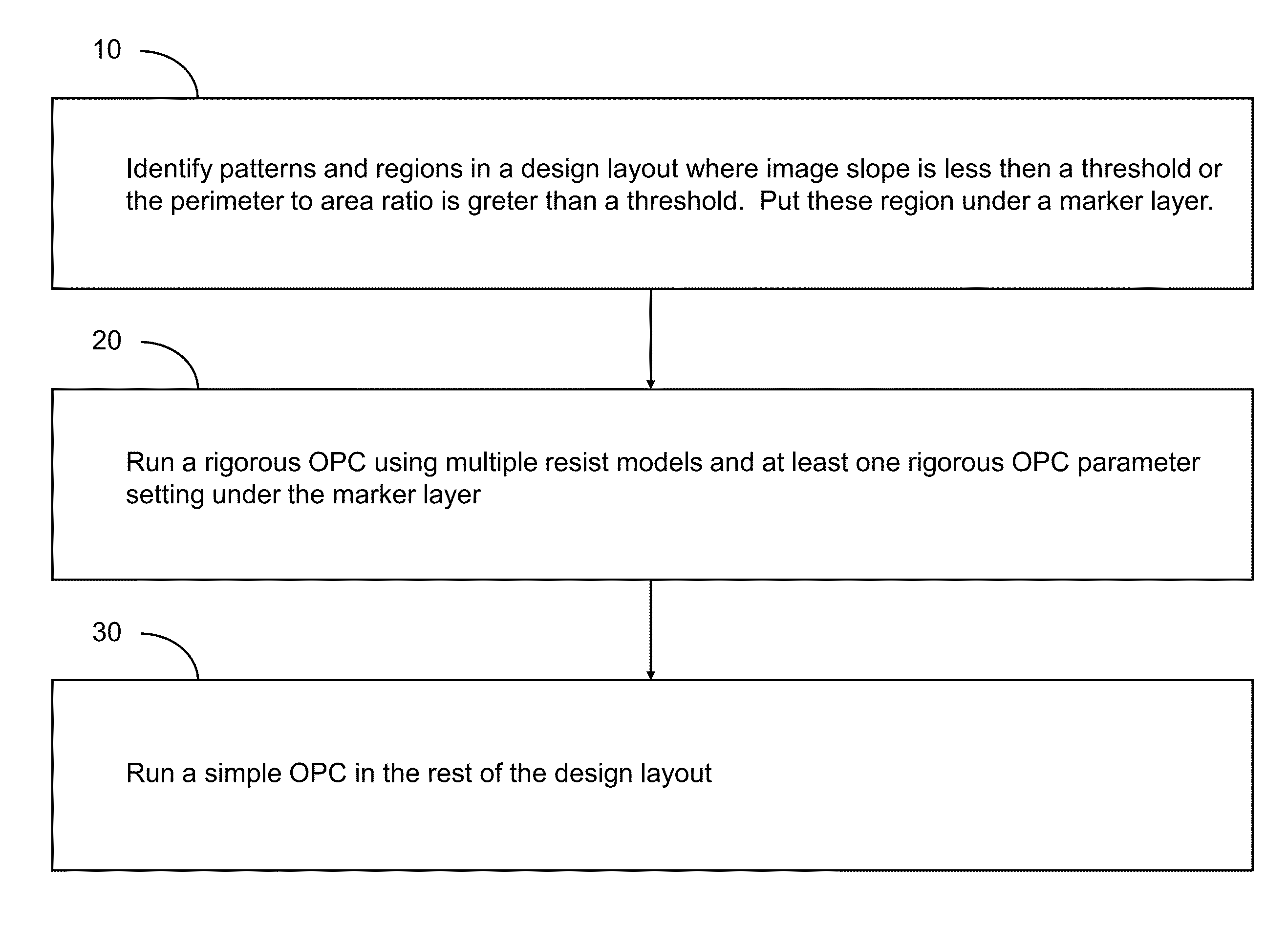
Further, because resist development characteristics and cross-sectional shapes are different at different process conditions corresponding to a different set of lithographic does and depth of focus, a single process model employing a single resist model does not represent the entire range of process variations.

Method used


Image

  • Optical proximity correction (OPC) methodology employing multiple OPC programs
  • Optical proximity correction (OPC) methodology employing multiple OPC programs
  • Optical proximity correction (OPC) methodology employing multiple OPC programs

Examples


Embodiment Construction

[0026]As stated above, the present disclosure relates to a methodology for optical proximity correction (OPC) that employs multiple OPC programs based on multiple process models and a system for implementing the same, which is now described in detail with accompanying figures. Like and corresponding elements mentioned herein and illustrated in the drawings are referred to by like reference numerals. The drawings are not necessarily drawn to scale.

[0027]As used herein, a “design clip” refers to a subset of a design layout for a semiconductor chip that is less than the entirety of the design layout.

[0028]As used herein, a “lithography process model” or a “process model” is a set of equations that are numerically computed, using an optical model first, to extract the light intensity distribution that is produced on the wafer surface by the imaging of the diffraction that results from a lithographic mask that is illuminated with a monochromatic light and via a system of lenses and / or mi...


PUM


Abstract

A marker layer is placed in regions of a design layout in which an image slope is less than a critical image slope or a perimeter to area ratio is less than a critical perimeter to area ratio. Multiple optical proximity correction (OPC) can be generated by grouping subsets of process conditions at which error mean and / or error root-mean-square (RMS) exceed threshold values. Regions marked with the marker layer are processed with a rigorous OPC employing at least one non-standard resist model, while unmarked regions of the layout are processes with a standard OPC program that is less rigorous than the at least one non-standard resist model. Additionally, number of edges and areal image contrast can be compared among layout clips to determine threshold values for the number of edges and the areal image contrast, which can be employed to determine if multiple OPC is needed for each layout clip.

Description

BACKGROUND[0001]The present disclosure relates to a methodology for optical proximity correction (OPC) that employs multiple OPC programs based on multiple process models and a system for implementing the same.[0002]OPC is employed to enable printing of lithographic shapes affected by the wave nature of irradiating light in lithographic processes. OPC is particularly useful when the lithographic shapes to be printed include sublithographic features, i.e., features having a dimension less than a minimum printable hole, line, or spacer.[0003]OPC methodology as known in the art typically employs a single OPC program employing a same set of parameters for the entire design layout. The set of parameters in an OPC program includes, for example, fragments and number of iterations. Further, OPC methodology as known in the art employs a single process model that is applied to the entirety of a design layout. The single process model includes a single resist model.[0004]Thus, the OPC methodol...

Claims


Application Information

Patent Timeline
Patent Type & Authority Patents(United States)
IPC IPC(8): G06F17/50
CPCG03F1/36
Inventor BARAI, SAMIT
Owner IBM CORP
Features
  • R&D
  • Intellectual Property
  • Life Sciences
  • Materials
  • Tech Scout
  • Unparalleled Data Quality
  • Higher Quality Content
  • 60% Fewer Hallucinations
Learn More