Air intake device for internal combustion engine
a technology for internal combustion engines and air intake devices, which is applied in the direction of air intakes for fuel, combustion-air/fuel-air treatment, machines/engines, etc. it can solve the problems of large amount of leakage air in a fully-closed state of the rotary valve, and suppress so as to prevent the flow rate of localized flow from slowing down, the effect of spreading the straight flow
- Summary
- Abstract
- Description
- Claims
- Application Information
AI Technical Summary
Benefits of technology
Problems solved by technology
Method used
Image
Examples
first embodiment
[0052](First Embodiment)
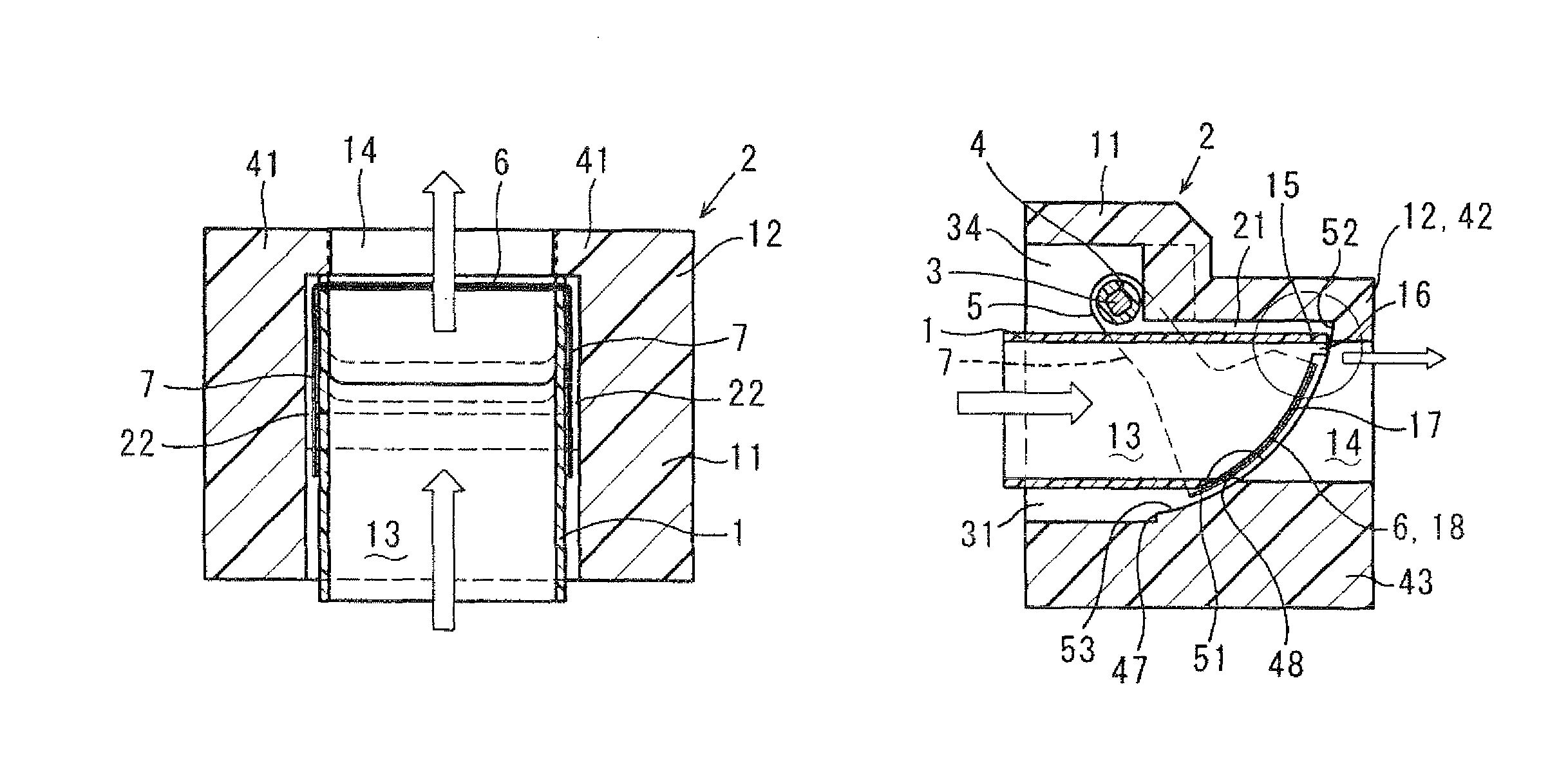
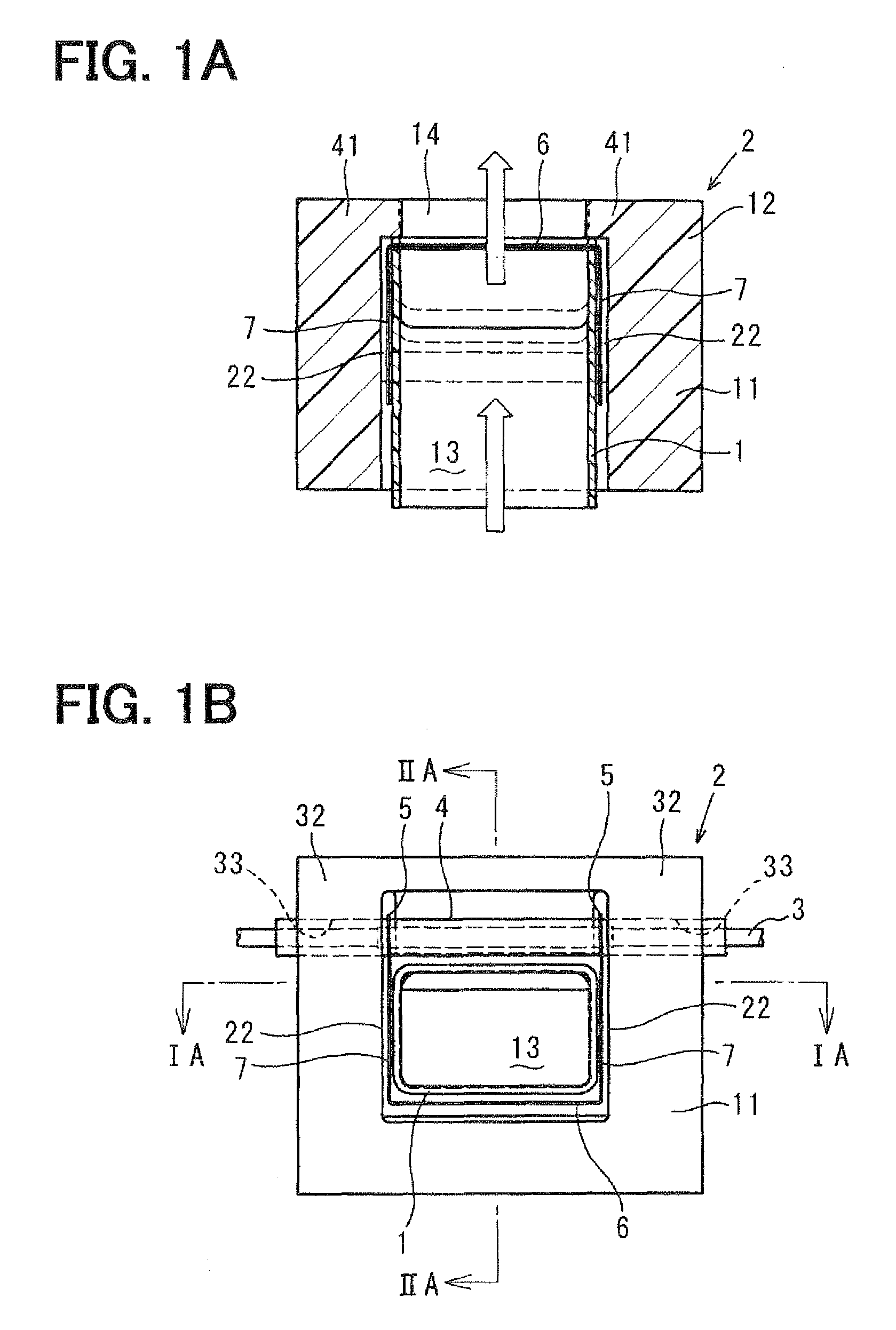
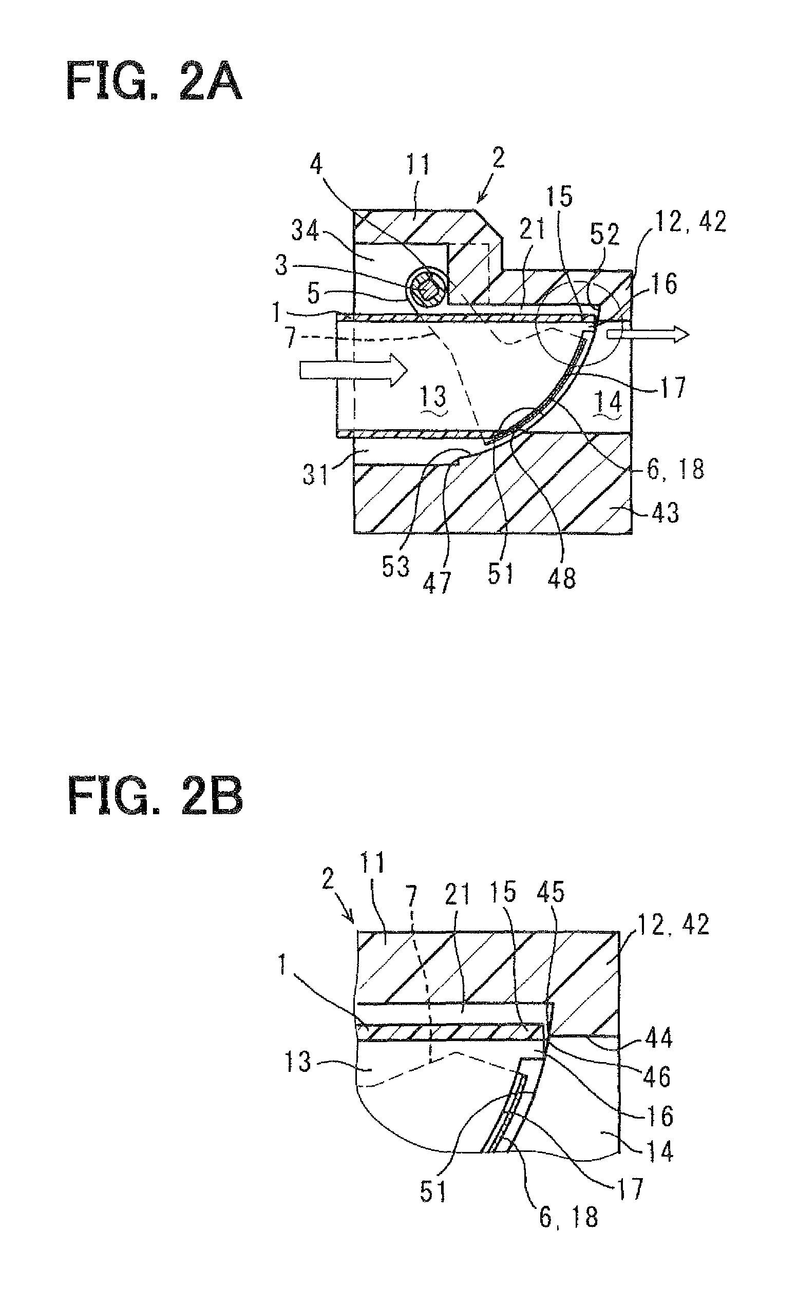
[0053]The first embodiment of the present invention is described with reference to FIGS. 1A to 3C. FIGS. 1A to 2B show a valve unit (TCV), and FIGS. 3A to 3C show a housing.
[0054]An air intake device for an internal combustion engine having multiple cylinders of the present embodiment includes multiple valve units, each of which is used as an intake air flow control valve (tumble flow control valve, i.e., TCV) housed in an intake pipe (intake duct) of the internal combustion engine (engine).
[0055]The valve unit includes a duct 1 made of synthetic resin, into which intake air which has flowed out of a throttle body or a surge tank flows, a housing 2 made of synthetic resin, which is arranged to surround the periphery of the duct 1, a rotating shaft (shaft 3 made of metal) which is rotatably supported by the housing 2, and two connecting portions 5 which are connected (support fixation) to a resin molding portion (shaft 4 made of synthetic resin), which covers ...
second embodiment
[0140](Second Embodiment)
[0141]The second embodiment of the present invention is described with reference to FIGS. 4A to 5. FIGS. 4A and 4B show a valve unit (TCV), and FIG. 5 shows a housing.
[0142]In the valve unit of the present embodiment, the duct 1 is inserted in and supported by the housing 2.
[0143]The housing 2 has the rectangular tube-shaped block 11, which is arranged to surround the periphery of the duct 1 in the circumferential direction, the rectangular tube-shaped block 12, which extends toward the downstream side (a side of the intake port) in the air flow direction than the downstream end of the block 11, and the like.
[0144]The upper wall 42 of the block 12 has a protruding wall (protrusion) 49, which protrudes toward the upstream side of the air flow passage 14 in the air flow direction so as to contact (adhere to) the duct protrusion 15 of the duct 1 (the downstream end of the duct 1 near the opening).
[0145]In the present embodiment, an end portion of the protruding...
third embodiment
[0147](Third Embodiment)
[0148]The third embodiment of the present invention is described with reference to FIGS. 6A to 7. FIGS. 6A and 6B show a valve unit (TCV), and FIG. 7 shows a housing.
[0149]In the valve unit of the present embodiment, the duct 1 is inserted in and supported by the housing 2.
[0150]The housing 2 has the rectangular tube-shaped block 11, which is arranged to surround the periphery of the duct 1 in the circumferential direction, the rectangular tube-shaped block 12, which extends toward the downstream side (a side of the intake port) in the air flow direction than the downstream end of the block 11, and the like.
[0151]The upper wall 42 of the block 12 has the protruding wall 44 that protrudes downward in the height direction from a wall surface of the upper wall 42 of the block 12. The protruding wall 44 has a protrusion 61, which protrudes toward the upstream side of the air flow passage 14 in the air flow direction so as to contact (adhere to) the duct protrusio...
PUM
 Abstract
Description
Claims
Application Information
 - R&D
- Intellectual Property
- Life Sciences
- Materials
- Tech Scout
- Unparalleled Data Quality
- Higher Quality Content
- 60% Fewer Hallucinations
Browse by: Latest US Patents, China's latest patents, Technical Efficacy Thesaurus, Application Domain, Technology Topic, Popular Technical Reports.
© 2025 PatSnap. All rights reserved.Legal|Privacy policy|Modern Slavery Act Transparency Statement|Sitemap|About US| Contact US: help@patsnap.com


