Supercharge Your Innovation With Domain-Expert AI Agents!

Multispectral uncooled thermal infrared camera system

a multi-spectral infrared and thermal infrared technology, applied in the field of uncooled multi-spectral infrared camera systems, can solve the problems of high cost of commercial camera systems designed to collect multi-spectral imagery, the difficulty of using commercial spectral filters with microbolometer cameras, and the inability to cool quantum detectors cryogenically

Inactive Publication Date: 2013-06-18
OPTO KNOWLEDGE SYST
View PDF19 Cites 9 Cited by
  • Summary
  • Abstract
  • Description
  • Claims
  • Application Information

AI Technical Summary

Benefits of technology

The invention solves the issue of background flux in a thermal IR camera by using filters tilted at an angle to prevent radiation from a warm detector from being reflected back into itself, a cooling system for the filter housing to prevent stray radiation, and cooling filters to reduce thermal emission. A multi-spectral camera system includes a cooled housing that shields the filters in front of a warm detector, with filters inclined at an angle and a reflective surface to absorb stray radiation. The system achieves high-quality infrared imaging and reduces parasitic radiation incident on the detector.

Problems solved by technology

Most commercial camera systems designed to collect multi-spectral imagery (i.e., images at two to several discrete wavelength bands) utilize cryogenically cooled quantum type detectors and, as a consequence, are expensive.
Such filters are referred to as “spectrally selective.” However, using those commercial spectral filters with microbolometer cameras poses a challenge since the filters transmit only over a certain portion (e.g., the band-pass) of the spectrum, but reflect and / or emit radiation at all other regions of the spectrum.
In such cameras the filter is also cold.
As a consequence, a microbolometer camera with a band pass filter positioned in front of the camera has a relatively large amount of parasitic radiation that is not useful for imaging.
The parasitic radiation may be subtracted using an offset correction; however, the process may be only partially effective because of the introduction of radiation that degrades the image quality by limiting the dynamic range of the detector to avoid saturation.

Method used


Image

  • Multispectral uncooled thermal infrared camera system
  • Multispectral uncooled thermal infrared camera system
  • Multispectral uncooled thermal infrared camera system

Examples


Embodiment Construction

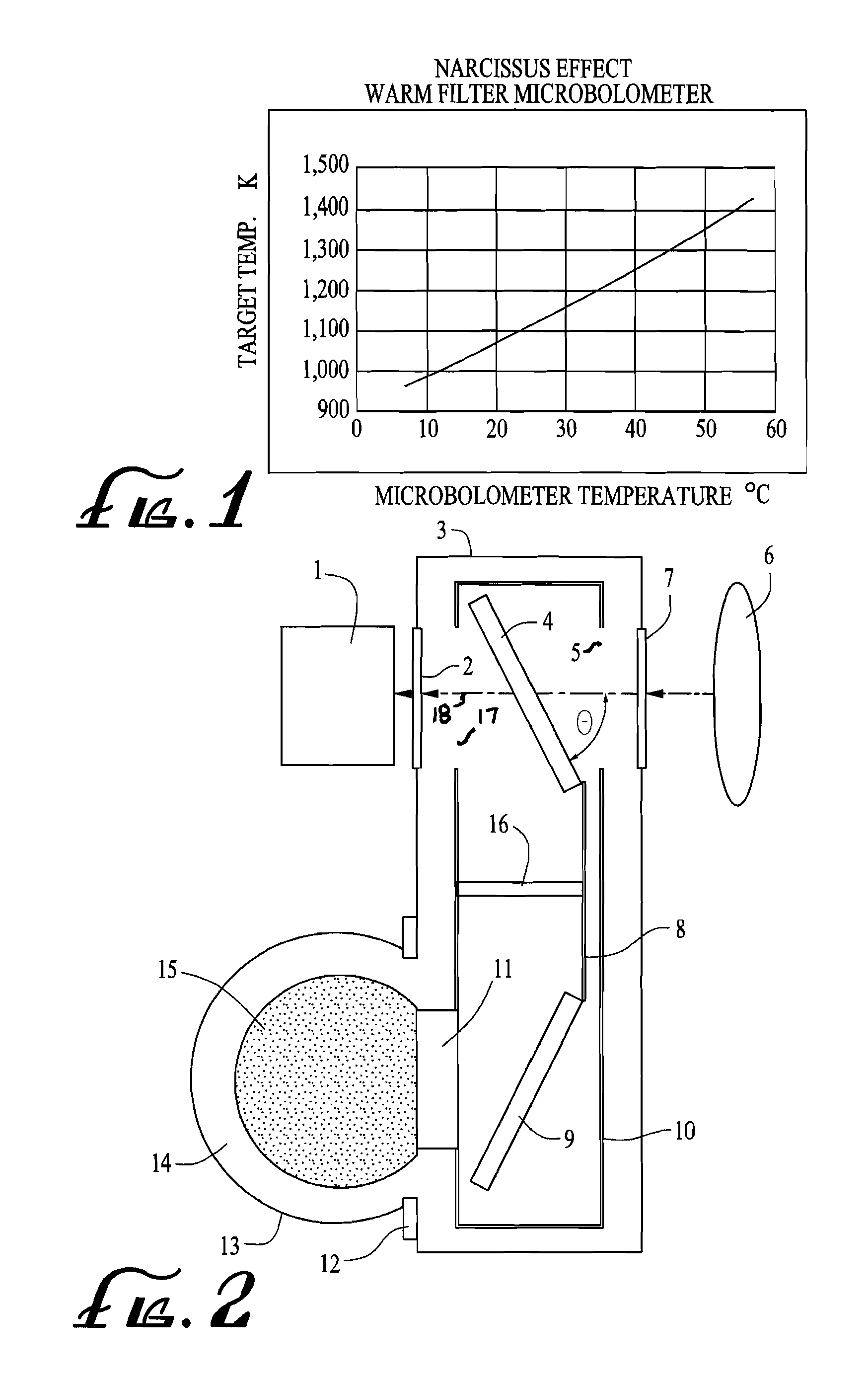
[0027]In one salient feature of the present invention, an uncooled infrared camera system described herein below produces images of a scene or object in the thermal infrared region. The uncooled infrared camera uses a lens to capture and focus the thermal infrared radiation emitted by the scene or the object. The focused radiation is converted from photons or electromagnetic wave to electrical signal via a “detector”. The detector uses a “sensor” that works by a change in resistance, voltage, capacitance, or current when heated by infrared radiation. These changes are measured and compared to values at the reference condition of the sensor. In one embodiment, the sensor utilizes a matrix sensor array (e.g., 1024×1024 “pixels”) to produce an electronic image of the scene. The matrix sensor array, occupies a position at the focal plane of the lens (often called FPA—focal plane array, or alternatively an IRFPA—InfraRed FPA).

[0028]As part of an exemplary embodiment, a matrix sensor arra...


PUM


Abstract

A multispectral thermal infrared camera system is disclosed. An uncooled thermal imaging camera is equipped with an axially tilted, cooled spectral filter. The axially tilted, cooled spectral filter deflects the radiation emitted by the uncooled camera away from being reflected back into the camera. The axially tilted, cooled spectral filter emits a lesser amount of thermal radiation towards the camera. And the axially tilted, cooled tilted filter is enclosed in a cold radiation shield to minimize the thermal emission that would be reflected by the filter towards the camera and to absorb the radiation deflected by the tilted filter. The axially tilted, cooled spectral filter passes only the desired portion of the thermal infrared radiation from the scene onto the uncooled camera.

Description

PRIORITY APPLICATION[0001]This application claims priority to the U.S. provisional application Ser. No. 60,921,527 filed with the United States Patent and Trademark Office on Apr. 2, 2007, entitled “MULTISPECTRAL UNCOOLED THERMAL INFRARED CAMERA SYSTEM” by inventors Nahum Gat and Jason Kreisel, which is incorporated by reference herein in its entirety.STATEMENT OF GOVERNMENT RIGHTS[0002]This invention was made with U.S. Government support under Contract No. W15QKN-06-C-0211 awarded by the U.S. Department of the Defense. The U.S. Government has certain rights in this invention.FIELD OF THE INVENTION[0003]This invention relates to uncooled multi-spectral infrared camera systems, and, more particularly, to enhancing the quality of collected infra-red imagery at multiple spectrally selective states through the reduction of parasitic radiation. Parasitic radiation is defined here as radiation from all sources in the system and environment that is not related to the scene to be imaged.BAC...

Claims


Application Information

Patent Timeline
Patent Type & Authority Patents(United States)
IPC IPC(8): H04N5/33
CPCH04N5/33H04N23/23
Inventor GAT, NAHUMKRIESEL, JASON
Owner OPTO KNOWLEDGE SYST
Features
  • R&D
  • Intellectual Property
  • Life Sciences
  • Materials
  • Tech Scout
  • Unparalleled Data Quality
  • Higher Quality Content
  • 60% Fewer Hallucinations
Learn More