Communications apparatus

a technology of communication apparatus and communication channel, applied in the field of communication channel, can solve the problems of remarkable deterioration of communication quality and disabled capability

Inactive Publication Date: 2013-06-18
DENSO CORP
View PDF6 Cites 43 Cited by
  • Summary
  • Abstract
  • Description
  • Claims
  • Application Information

AI Technical Summary

Benefits of technology

[0014]Under such a configuration of the communications apparatus, the direction of the directional vector (i.e., direction in which the signal intensity is provided at maximum) can be suitably switched by selecting a driving electrode pair. The stable signal transmission can be thus achieved without relation to the attachment state of the apparatus (inclination at the attachment position, etc.) or the state of the wearing body or object (the contact position with the external apparatus, and posture if the wearing body is a human body, etc.).

Problems solved by technology

That is, the communications quality may be deteriorated remarkably or the capability may be disabled, depending on the above various states.

Method used


Image

  • Communications apparatus
  • Communications apparatus
  • Communications apparatus

Examples


first embodiment

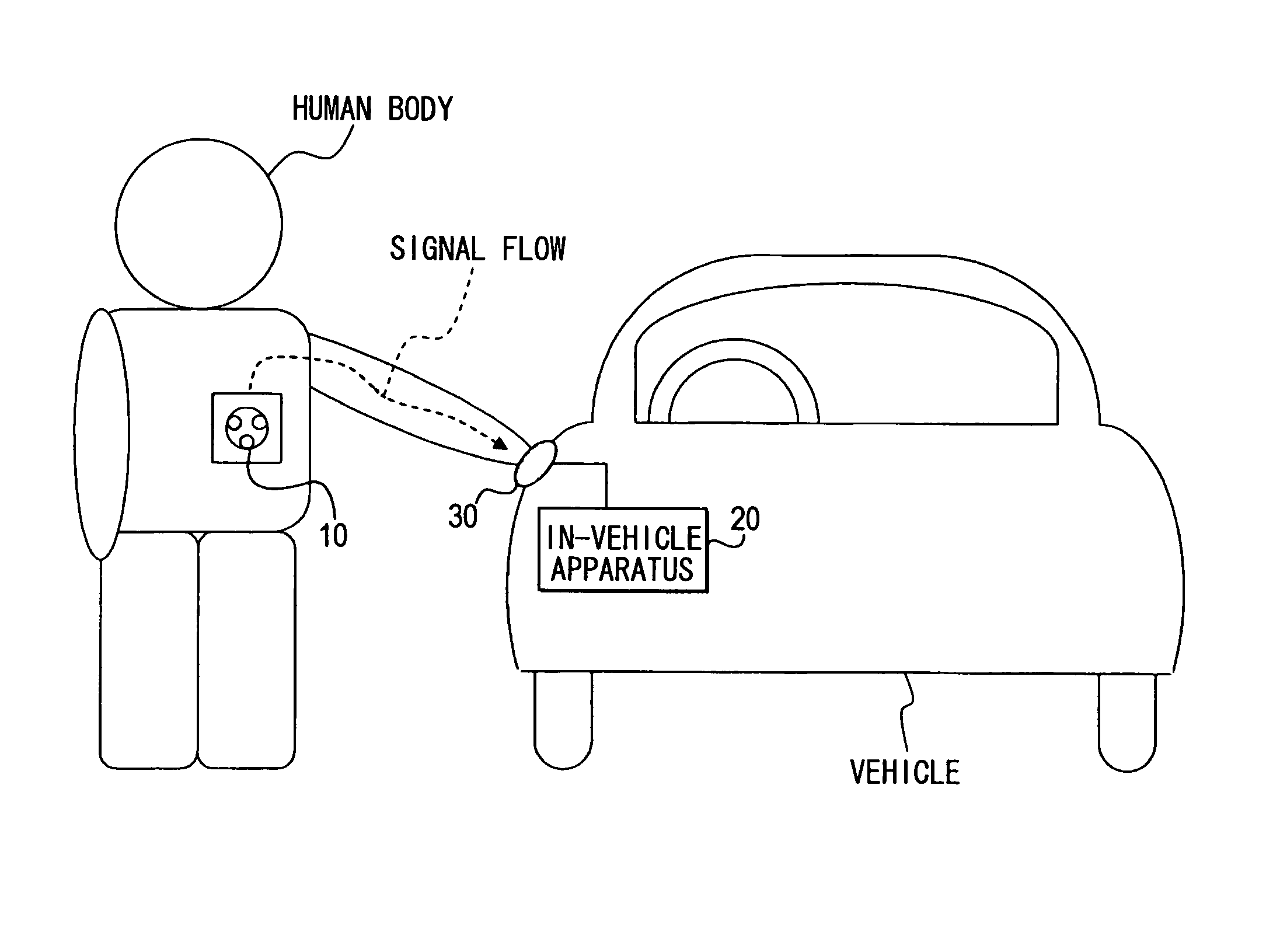
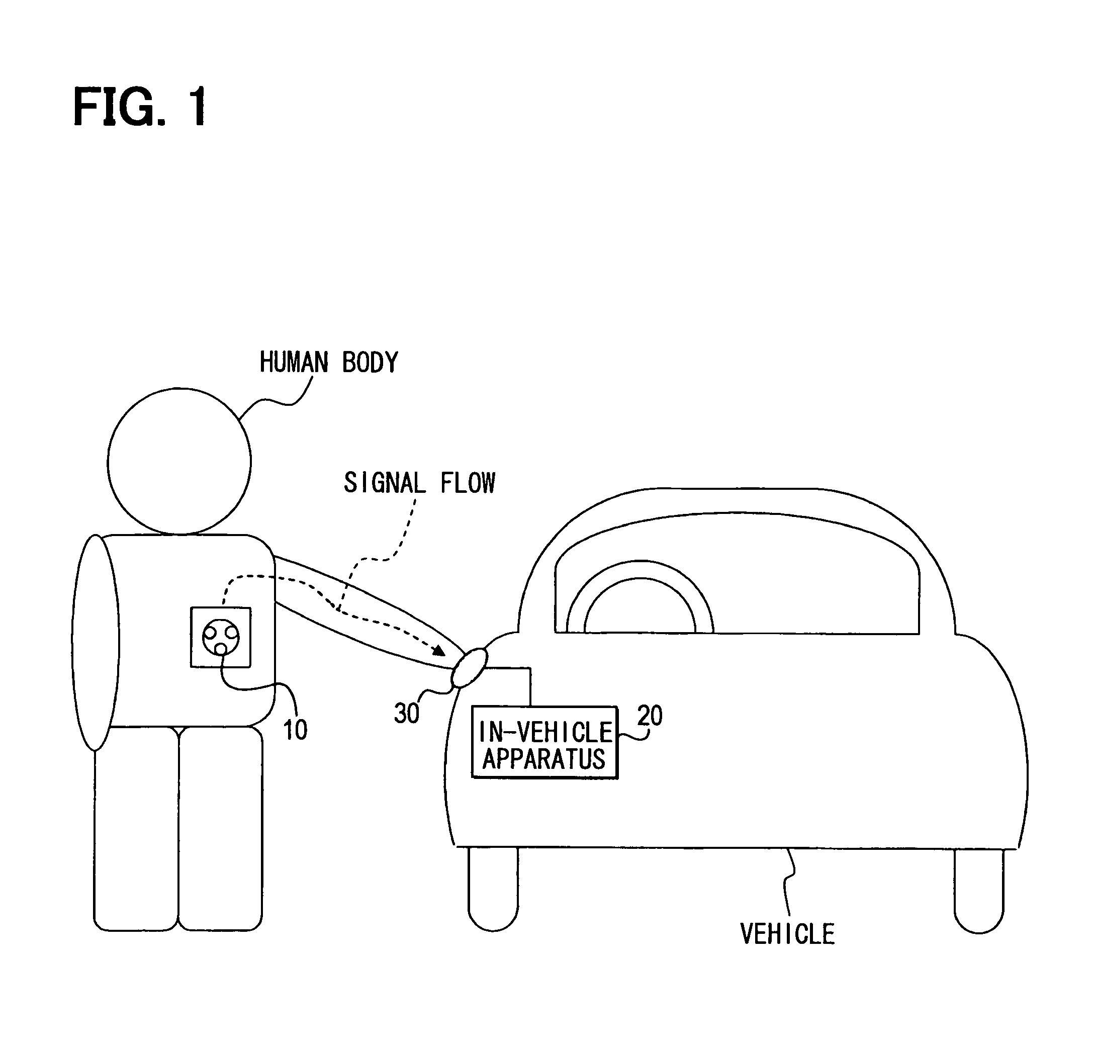
[0036]FIG. 1 is a diagram illustrating a schematic configuration of a smart entry system to which the present invention is directed. Further, the smart entry system includes a portable terminal, which can be referred to as a communications apparatus.

[0037]

[0038]The smart entry system for a subject vehicle includes the following: a portable terminal 10 shaped of a card; a vehicle-side electrode 30 provided in a door handle of a driver's seat door of the vehicle; and an in-vehicle apparatus 20. Herein, the portable terminal 10 is carried or worn by a user; in other words, the portable terminal 10 is used by accompanying a user or being attached to the user. The in-vehicle apparatus 20 executes intrabody communication (also referred to human body data communications) with the portable terminal 10 via the vehicle-side electrode 30 when the user carrying or wearing the portable terminal 10 touches the vehicle-side electrode 30.

[0039]It is noted that the portable terminal 10 stores, at le...

modification example

[0069]In the present embodiment, the driving electrode pair group includes the three types of driving electrode pairs P1 to P3. Without need to be limited thereto, other three types of driving electrode pairs may be provided by switching between the first driving electrode and the second driving electrode. That is, P4=(D2|D1), P5=(D3|D2), and P6=(D1|D3) are added, thereby forming the driving electrode pair group by six types of driving electrode pairs P1 to P6. In such a case, the directional vector can be changed every 60 degrees, only requiring the beam width of each electrode pair P1 to P6 to cover ±30 degrees.

[0070]In addition, in the present embodiment, each of the first driving electrode and the second driving electrode is configured as a single electrode. Without need to be limited thereto, as illustrated in FIG. 6, for instance, the first driving electrode can be configured or defined as a combination of two electrodes. That is, the driving electrode pair group may be provid...

second embodiment

[0074]The following describes a second embodiment of the present invention.

[0075]The portable terminal 10a of the present second embodiment is only different from the portable terminal 10 of the first embodiment in that a part of the configuration and the transmission process executed by the control circuit 17. The following thus mainly explains such a different point. Furthermore, a reception process is explained which is necessary for the in-vehicle apparatus 20 in conjunction with the change in the transmission process.

[0076]

[0077]FIG. 7 is a block diagram illustrating an internal configuration of the portable terminal 10a (i.e., communications apparatus).

[0078]As illustrated in FIG. 7, the portable terminal 10a is configured similar to the portable terminal 10 of the first embodiment, except that a reception circuit 16 is added so as to receive a reception signal from the in-vehicle apparatus 20 (i.e., acquired from the transmission medium) via the driving electrode pair selecte...


PUM


Abstract

An electrode group is provided in a portable terminal carried by a human body for transmitting a transmission signal to the human body functioning as a transmission medium. The electrode group contains three electrodes arranged respectively at three vertices of an equilateral triangle. Three types of driving electrode pairs are defined as respectively having different combination of optional two electrodes. While changing the driving electrode pairs for use in order one pair by one pair, the transmission signal based on the same transmission data is repeatedly transmitted as many times as the number of driving electrode pairs.

Description

CROSS REFERENCE TO RELATED APPLICATION[0001]The present application is based on and incorporates herein by reference Japanese Patent Application No. 2009-63867 filed on Mar. 17, 2009.FIELD OF THE INVENTION[0002]The present invention relates to a communications apparatus which carries out data communications by using a human body as a transmission medium. Furthermore, the present invention relates to a smart entry system for a vehicle using the above communications apparatus and a method for controlling data communications taking place in the above communications apparatus.BACKGROUND OF THE INVENTION[0003][Patent document 1] JP-2007-6420 A[0004][Non-patent document 1] K. Ito and M. Takahashi, and K. Fujii: Transmission Mechanism of Wearable Devices Using the Human Body as a Transmission Channel, in “Antennas and Propagation for Body-Centric Wireless Communications (Peter S. Hall and YangHao (Eds.)),” Artech House, pp. 65-92, 2006[0005]There is conventionally known a communications ap...

Claims


Application Information

Patent Timeline
Patent Type & Authority Patents(United States)
IPC IPC(8): H04B1/034
CPCH04B13/005
Inventor HACHISUKA, KEISUKESHIBATA, TAKAYUKISUGAWARA, RYOICHI
Owner DENSO CORP
Why Eureka
Try Eureka