Aerodynamic structure having a ridged solar panel and an associated method

a solar panel and aerodynamic technology, applied in the direction of energy-efficient board measures, air-flow influencers, pv power plants, etc., can solve the problems of increasing the weight and drag of aircraft, reducing the fuel efficiency of aircraft, and relatively low energy conversion efficiency, so as to increase the solar energy harvesting effect of solar panels, reduce drag, and fuel efficient

Active Publication Date: 2013-06-25
THE BOEING CO
View PDF8 Cites 17 Cited by
  • Summary
  • Abstract
  • Description
  • Claims
  • Application Information

AI Technical Summary

Benefits of technology

[0005]Air vehicles and associated aerodynamic structures that may be more fuel efficient are provided in accordance with embodiments of the present disclosure. In this regard, the air vehicle, aerodynamic structure and associated method of embodiments of the present disclosure may include ridged solar panels to both reduce the drag and increase the solar energy harvested by the solar panel. By reducing the drag and by increasing the electrical energy that may be generated from the solar energy collected by the solar panel, the air vehicle, aerodynamic structure and associated method of embodiments of the present disclosure may operate in a more fuel efficient manner.

Problems solved by technology

With rising fuel costs, there are increasing demands being placed upon aircraft to be more fuel efficient, that is, to go at least as far or further while consuming the same amount or less fuel.
However, the solar cells generally disadvantageously increase the weight and the drag of the aircraft and correspondingly reduce the fuel efficiency of the aircraft, notwithstanding the gains attributable to the harvesting of solar energy by the solar cells.
Additionally, the relatively low energy conversion efficiency and the relatively high surface area to power output ratio of solar cells has also limited their utilization as an alternative energy source for aircraft.

Method used


Image

  • Aerodynamic structure having a ridged solar panel and an associated method
  • Aerodynamic structure having a ridged solar panel and an associated method

Examples


Embodiment Construction

[0018]The present disclosure now will be described more fully hereinafter with reference to the accompanying drawings, in which some, but not all embodiments are shown. Indeed, the present disclosure may be embodied in many different forms and should not be construed as limited to the embodiments set forth herein; rather, these embodiments are provided so that this disclosure will satisfy applicable legal requirements. Like numbers refer to like elements throughout.

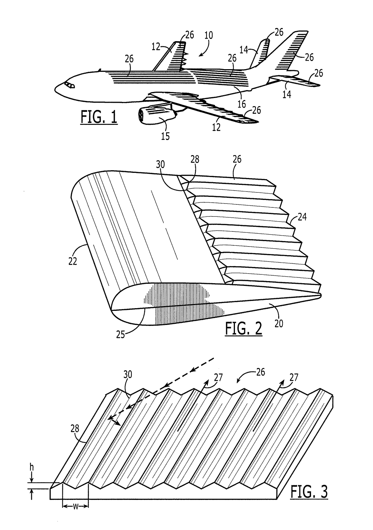
[0019]Referring to FIG. 1, an air vehicle 10 in accordance with one embodiment is illustrated. Although the air vehicle of the illustrated embodiment is an aircraft, a variety of other types of air vehicles may be employed in accordance with embodiments of the present disclosure, including missiles. Even with respect to aircraft, the aircraft of embodiments of the present disclosure may be widely varied, including both commercial and military aircraft and manned and unmanned aircraft.

[0020]An air vehicle 10 includes an ai...


PUM


Abstract

Air vehicles and associated aerodynamic structures are provided which include ridged solar panels to both reduce the drag and increase the solar energy harvested by the solar panel. The air vehicle may include an airframe and a solar panel carried by the airframe and defining an exterior surface thereof. The solar panel may include a plurality of ridged structures extending in a lengthwise direction. The ridged structures may be arranged such that a majority of the airflow over the exterior surface flows in the lengthwise direction. The plurality of ridged structures may include a plurality of lengthwise extending projections spaced about by respective valleys.

Description

TECHNOLOGICAL FIELD[0001]Embodiments of the present disclosure relate generally to air vehicles and associated aerodynamic structures and, more particularly, to air vehicles and associated aerodynamic structures having solar panels for the generation of electrical energy.BACKGROUND[0002]With rising fuel costs, there are increasing demands being placed upon aircraft to be more fuel efficient, that is, to go at least as far or further while consuming the same amount or less fuel. By becoming more fuel efficient, the costs associated with the fuel consumption of a fleet of aircraft would be reduced, and the impact upon the environment would be correspondingly decreased. Additionally, a more fuel efficient aircraft carrying the same amount of fuel could carry a greater payload and / or have a greater mission range or time. In order to construct aircraft having improved fuel efficiency, a variety of techniques to reduce the drag and therefore increase the fuel efficiency of an aircraft hav...

Claims


Application Information

Patent Timeline
Patent Type & Authority Patents(United States)
IPC IPC(8): B64C1/38
CPCB64C23/06B64D41/00B64D2211/00H01L31/0236H02S10/40Y02E10/50Y02T50/10Y02T50/50
Inventor DONG, JIAN
Owner THE BOEING CO
Why Eureka
Try Eureka