Substrate treatment method, computer storage medium and substrate treatment apparatus

a technology of substrate treatment and computer storage medium, applied in the direction of pliable tubular containers, instruments, photosensitive materials, etc., can solve the problems of development defects still occurring depending on the kind of applied resist, and achieve the effect of reducing the number of defects on the substrate surfa

Active Publication Date: 2013-06-25
TOKYO ELECTRON LTD
View PDF7 Cites 0 Cited by
  • Summary
  • Abstract
  • Description
  • Claims
  • Application Information

AI Technical Summary

Benefits of technology

[0011]The present invention has been made in consideration of the above points, and it object is to reduce defects on a substrate surface by removing air bubbles occurring between the substrate and a surface treatment liquid when the surface treatment liquid is supplied onto the substrate.
[0013]According to the present invention, when the surface treatment liquid is first supplied to one location of the peripheral portion of the substrate, a liquid puddle is formed at a position where the supplied surface treatment liquid lands on the substrate, and small air bubbles occur between the liquid puddle and the substrate. Then, by moving the nozzle to a position above the central portion of the substrate while continuing the supply of the surface treatment liquid, the liquid puddle formed at the peripheral portion of the substrate is moved to the central portion of the substrate, so that the air bubbles existing between the substrate and the surface treatment liquid can be exposed to the outside and removed. Therefore, according to the present invention, the air bubbles occurring between the substrate and the surface treatment liquid when the surface treatment liquid is supplied onto the substrate never inhibit the contact between, for example, the resist film and the developing solution. Therefore, defects on the substrate surface can be reduced.

Problems solved by technology

However, even when using the method of the above-described Patent Document 1, development defects still occurred depending on the kind of the applied resist.

Method used


Image

  • Substrate treatment method, computer storage medium and substrate treatment apparatus
  • Substrate treatment method, computer storage medium and substrate treatment apparatus
  • Substrate treatment method, computer storage medium and substrate treatment apparatus

Examples


Embodiment Construction

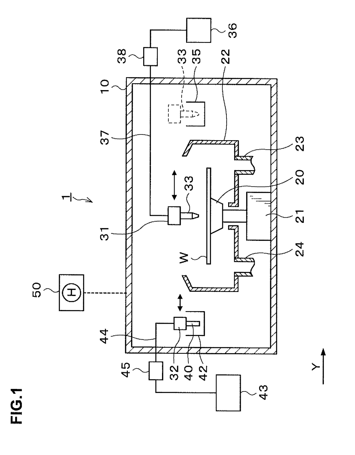
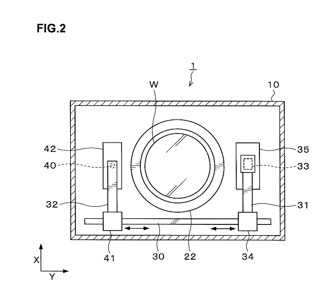
[0033]Hereinafter, an embodiment of the present invention will be described. FIG. 1 is a longitudinal sectional view illustrating the outline of the configuration of a developing treatment apparatus 1 as a substrate treatment apparatus according to this embodiment. FIG. 2 is a transverse sectional view illustrating the outline of the configuration of the developing treatment apparatus 1. Note that the diameter of the wafer W used as the substrate in this embodiment is 300 mm.

[0034]The developing treatment apparatus 1 has a treatment container 10 as illustrated in FIG. 1. At the central part in the treatment container 10, a spin chuck 20 as a rotating and holding unit is provided which holds and rotates the wafer W thereon. The spin chuck 20 has a horizontal upper surface which is provided with, for example, a suction port (not illustrated) for sucking the wafer W. Suction through the suction port enables the wafer W to be suction-held on the spin chuck 20.

[0035]The spin chuck 20 has...


PUM

PropertyMeasurementUnit
distanceaaaaaaaaaa
diameteraaaaaaaaaa
width L2aaaaaaaaaa

Abstract

The present disclosure is a substrate treatment method of supplying a surface treatment liquid onto a surface of a substrate having a film with high water repellency formed thereon, the method including: a liquid puddle forming step of forming a liquid puddle of the surface treatment liquid by supplying the surface treatment liquid from a nozzle to one location of a peripheral portion of the substrate; and a liquid puddle moving step of then moving the liquid puddle formed at the peripheral portion of the substrate to a central portion of the substrate by moving the nozzle from a position above the peripheral portion of the substrate to a position above the central portion of the substrate while continuing the supply of the surface treatment liquid.

Description

BACKGROUND OF THE INVENTION[0001]1. Field of the Invention[0002]The present invention relates to a method of treating a substrate having a film with high water repellency formed thereon, a computer storage medium and a substrate treatment apparatus.[0003]2. Description of the Related Art[0004]For example, in a photolithography process in manufacturing processes of a semiconductor device, for example, resist coating treatment for forming a resist film by applying a resist solution onto a semiconductor wafer (hereinafter, referred to as a “wafer”), exposure processing for exposing the resist film to a predetermined pattern, developing treatment for developing the exposed resist film and so on are sequentially performed, whereby a predetermined resist pattern is formed on the wafer.[0005]Regarding the above-described developing treatment of the resist film, there is a widely known method of supplying a developing solution from a nozzle to the central portion of the wafer while the wafe...

Claims


Application Information

Patent Timeline
Patent Type & Authority Patents(United States)
IPC IPC(8): G03D5/00
CPCG03F7/3021H01L21/67051H01L21/6715G03F7/38H01L21/0274
Inventor TAKEGUCHI, HIROFUMIYOSHIDA, YUICHI
Owner TOKYO ELECTRON LTD
Why Eureka
Try Eureka