Battery state monitoring circuit and battery device

a battery state monitoring and circuit technology, applied in battery overheat protection, safety/protection circuits, instruments, etc., can solve the problem that the current consumption of the comparator is small enough to not hinder the operation of automatic recovery, and achieve the effect of preventing the operation

Inactive Publication Date: 2013-06-25
ABLIC INC
View PDF13 Cites 7 Cited by
  • Summary
  • Abstract
  • Description
  • Claims
  • Application Information

AI Technical Summary

Benefits of technology

[0009]The present invention has been made to solve the problem described above, and provides a battery state monitoring circuit in which an automatic recovery function normally works, thereby being capable of lowering power consumption, and also provides a battery device including the battery state monitoring circuit.
[0012]According to the battery device of the present invention, it is possible to suspend the operation of the temperature sensor circuit until the voltage of the overcurrent detection terminal becomes higher than a voltage of a positive terminal of the secondary battery, that is, until the connection of a charger is established. As a result, the function of automatic recovery from an overcurrent protection state can normally work. The comparator obtains power from the output of the automatic recovery circuit, that is, from the overcurrent detection terminal. However, the current consumption of the comparator is tiny enough not to hinder the operation of the automatic recovery.

Problems solved by technology

However, the current consumption of the comparator is tiny enough not to hinder the operation of the automatic recovery.

Method used


Image

  • Battery state monitoring circuit and battery device
  • Battery state monitoring circuit and battery device
  • Battery state monitoring circuit and battery device

Examples


first embodiment

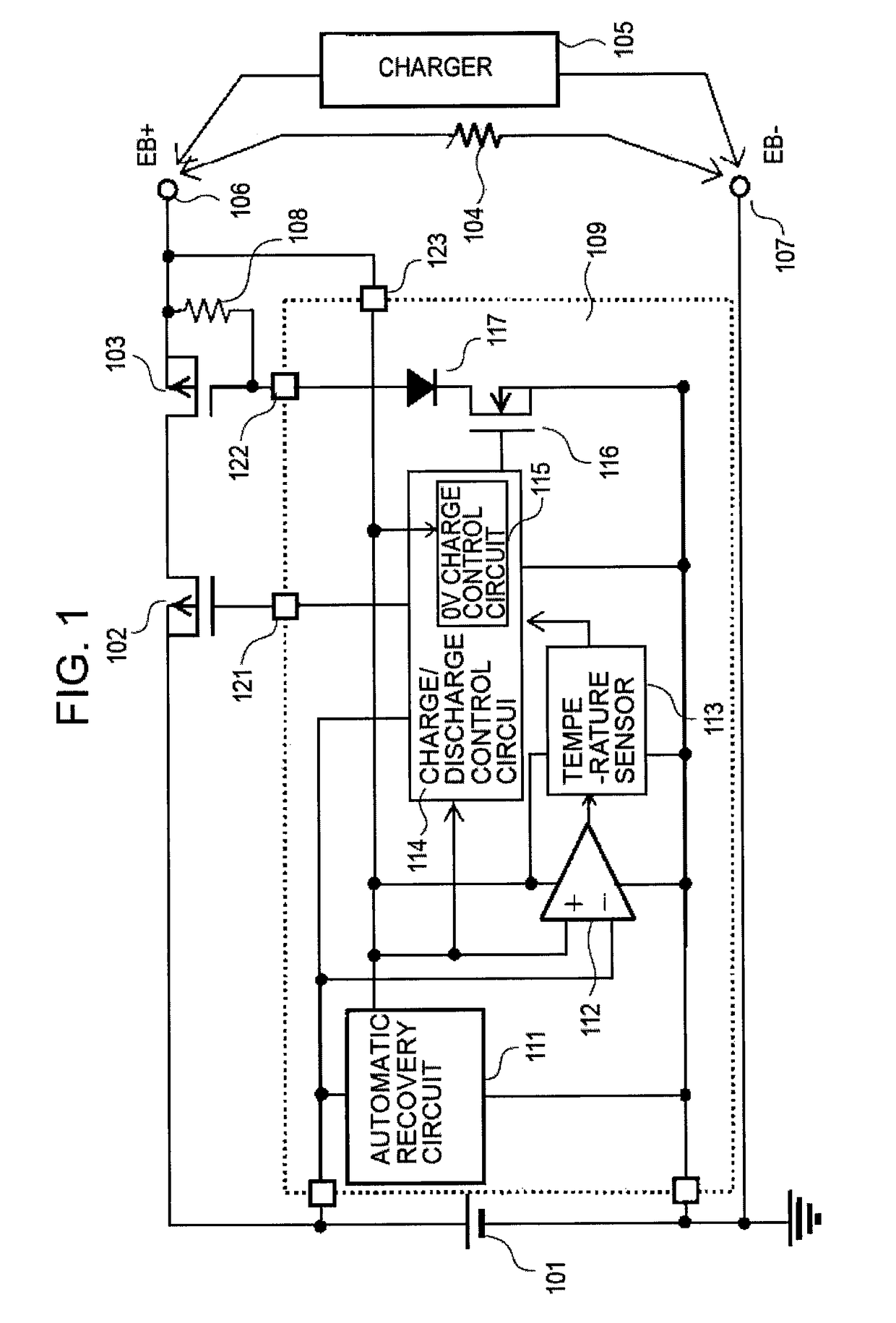
[0018]FIG. 1 is a circuit diagram of a battery device including a battery state monitoring circuit according to a first embodiment of the present invention.

[0019]The battery device according to the first embodiment includes a secondary battery 101, a battery state monitoring circuit 109, a discharge control P-channel field-effect transistor (FET) 102, a charge control P-channel FET 103, external terminals 106 and 107 to which a load 104 or a charger 105 is to be connected, a resistor 108. The battery state monitoring circuit 109 includes an automatic recovery circuit 111, a comparator 112, a temperature sensor circuit 113, a charge / discharge control circuit 114, a 0 V charge control circuit 115, an NMOS transistor 116, and a diode 117.

[0020]The automatic recovery circuit 111 and the charge / discharge control circuit 114 use the secondary battery 101 as power supply. The comparator 112, the temperature sensor circuit 113, and the 0 V charge control circuit 115 are each connected to an...

second embodiment

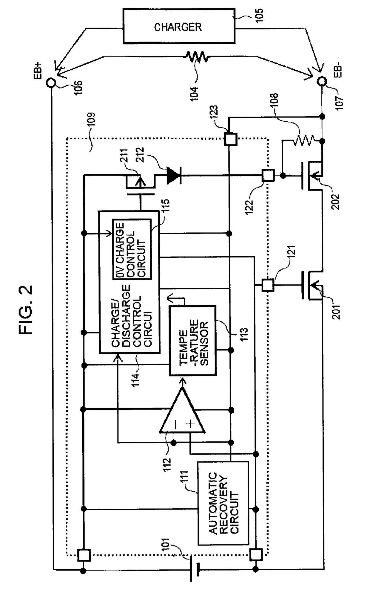
[0029]FIG. 2 is a circuit diagram of a battery device including a battery state monitoring circuit according to a second embodiment of the present invention. FIG. 2 is different from FIG. 1 in that the discharge control P-channel FET 102, the charge control P-channel FET 103, the NMOS transistor 116, and the diode 117 are changed to a discharge control N-channel FET 201, a charge control N-channel FET 202, a PMOS transistor 211, and a diode 212, respectively.

[0030]Connection is made as follows. The automatic recovery circuit 111 and the charge / discharge control circuit 114 use the secondary battery 101 as power supply. The comparator 112, the temperature sensor circuit 113, and the 0 V charge control circuit 115 are each connected to the overcurrent detection terminal 123 for negative power supply and connected to the positive terminal of the secondary battery 101 for positive power supply.

[0031]The PMOS transistor 211 has a gate connected to the output of the charge / discharge contr...


PUM


Abstract

Provided is a battery state monitoring circuit including: a charge / discharge control circuit for detecting and controlling a state of a secondary battery; an automatic recovery circuit; a temperature sensor circuit; and a comparator for comparing a voltage of an output terminal of the automatic recovery circuit and a voltage of the secondary battery, and outputting a signal indicative of a result of the comparison to the temperature sensor circuit, to control an operation of the temperature sensor circuit. The temperature sensor circuit operates only when the output of the automatic recovery circuit is larger, that is, only when a charger is connected between external terminals.

Description

RELATED APPLICATIONS[0001]This application claims priority under 35 U.S.C. §119 to Japanese Patent Application No. 2010-065138 filed on Mar. 19, 2010, the entire content of which is hereby incorporated by reference.BACKGROUND OF THE INVENTION[0002]1. Field of the Invention[0003]The present invention relates to a battery state monitoring circuit for detecting a voltage and an abnormality of a secondary battery and a battery device including the battery state monitoring circuit, and more particularly, to a battery state monitoring circuit incorporating a temperature sensor in a charge / discharge control circuit and a battery device including the battery state monitoring circuit.[0004]2. Description of the Related Art[0005]FIG. 3 illustrates a circuit diagram of a conventional battery device incorporating a temperature sensor. The conventional battery device incorporating the temperature sensor includes a secondary battery 101, a battery state monitoring circuit 309, an external termina...

Claims


Application Information

Patent Timeline
Patent Type & Authority Patents(United States)
IPC IPC(8): H02J7/00G01R31/36
CPCH01M10/486H02J7/0091H02J7/0031G01R31/3606G01R31/382H02J7/00309Y02E60/10H02J7/007194H02J7/00304G01R19/165G01R31/36
Inventor YOSHIKAWA, KIYOSHI
Owner ABLIC INC
Why Eureka
Try Eureka