

Finned cylindrical heat exchanger
a heat exchanger and cylindrical technology, applied in indirect heat exchangers, tubular elements, lighting and heating apparatus, etc., can solve the problems of increased likelihood of failure of this type of heat exchanger, and limited heat transfer in the tube bundle structur
- Summary
- Abstract
- Description
- Claims
- Application Information
AI Technical Summary
Benefits of technology
Problems solved by technology
Method used
Image

Examples
first embodiment
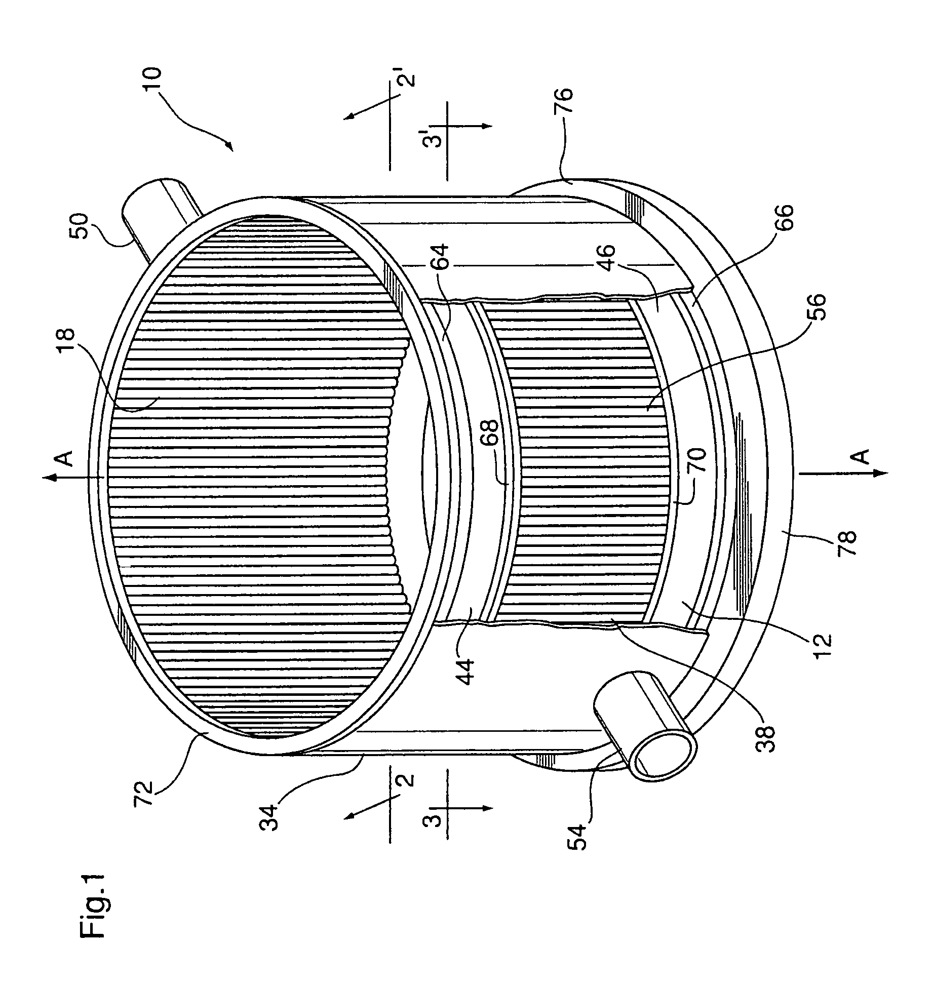
[0025]Illustrated in FIG. 1 is a heat exchanger 10 according to the invention. Heat exchanger 10 is generally in the shape of an open-ended, hollow cylinder having a sidewall which is comprised of at least three generally cylindrical layers. The sidewall of heat exchanger 10 extends parallel to a longitudinal axis A passing centrally through the hollow interior space of heat exchanger 10. In the following description, the terms such as “axial” and the like refer to directions which are parallel to the axis A, and terms such as “inner”, “outer”, “inward” and “outward” and the like refer to radial directions extending outwardly from or inwardly toward axis A, and which are transverse to axis A.
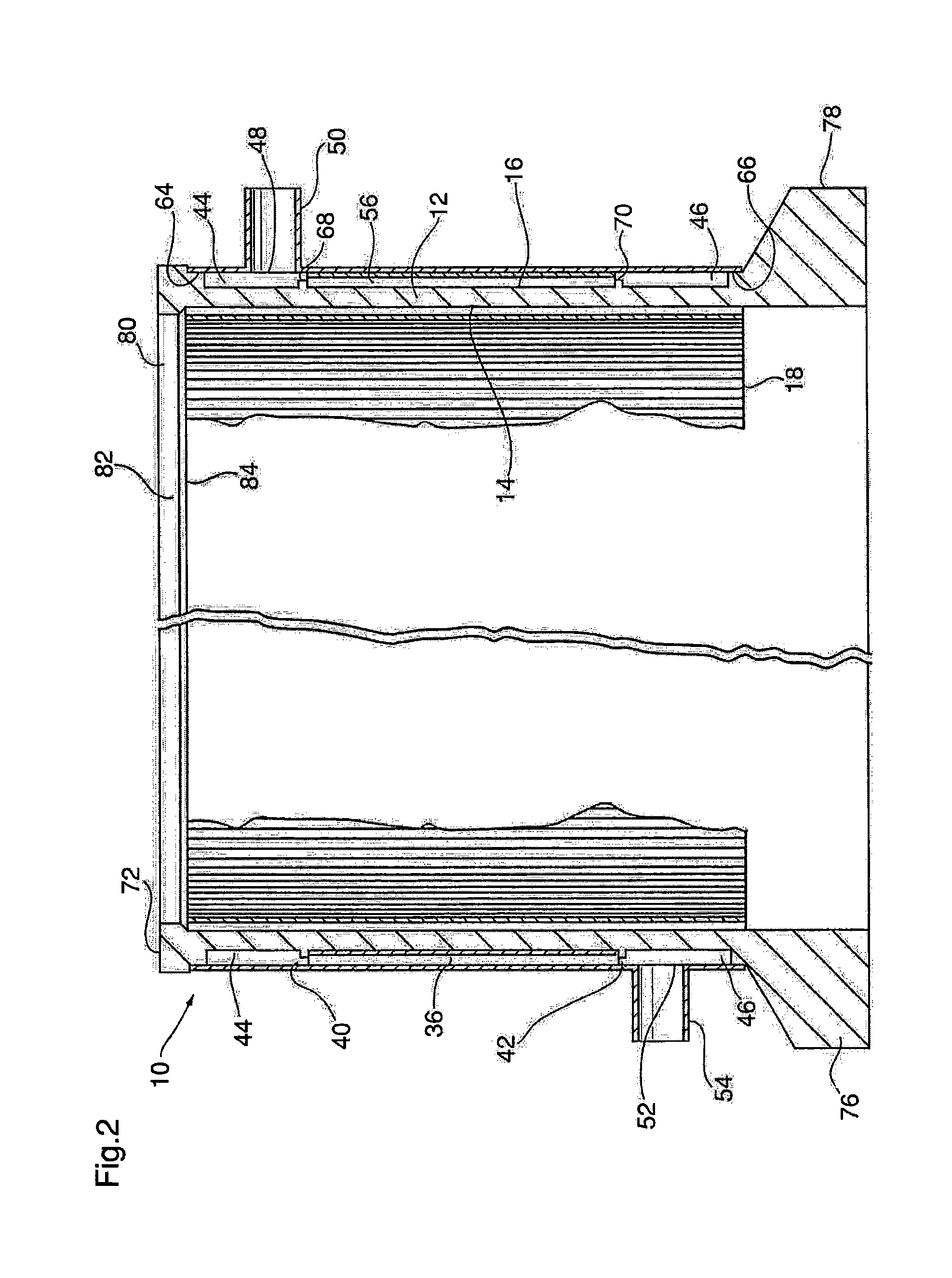
[0026]Heat exchanger 10 includes a cylindrical middle wall 12, best seen in FIG. 2, which is open at both ends and parallel to axis A. The middle wall 12 has an inner surface 14 and an opposed outer surface 16, both of which may be smooth and free of perforations. Where the heat exchanger 10 is ...
second embodiment
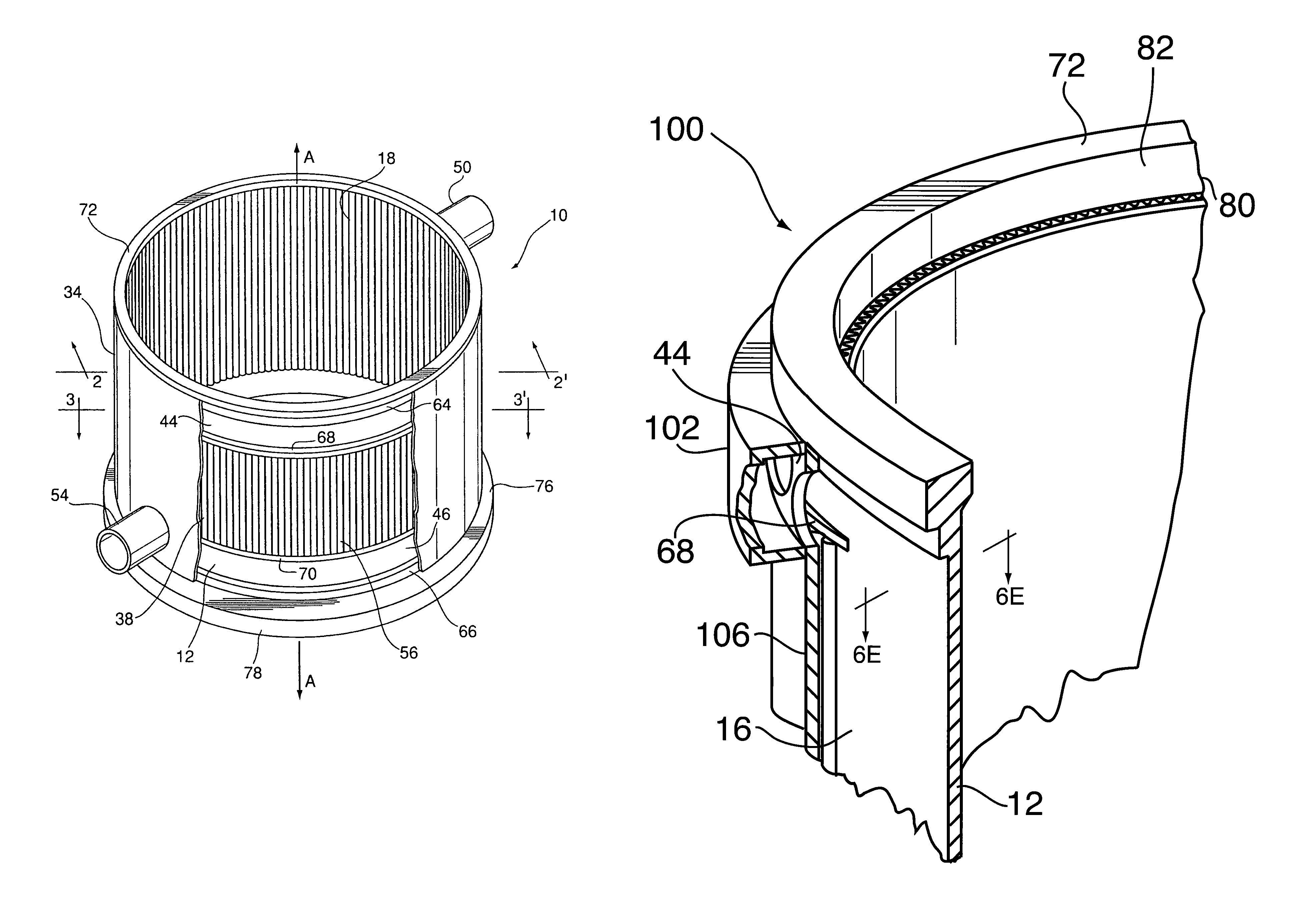
[0048]FIGS. 6 and 6A are partial cross-sectional views illustrating two variants of a heat exchanger 100 according to the invention. Most of the components of heat exchanger 100 are similar or identical to components of heat exchanger 10 described above, and therefore like reference numerals are used to describe like components in the following description.
[0049]Heat exchanger 100 includes a middle wall 12, an inner wall 18 in the form of a corrugated fin which partially defines a first fluid flow passage 22, an outer wall 34, and an intermediate outer wall 56 in the form of a corrugated fin located within a second fluid flow passage 38 having open ends 40, 42. Rather than being smooth as in heat exchanger 10, however, the outer wall 34 of heat exchanger 100 is provided with radially projecting portions 102, 104 which define the respective manifolds44 and 46. The radially projecting portions 102, 104 are separated by a smooth, cylindrical wall portion 106 of outer wall 34 which is i...
third embodiment
[0057]FIGS. 7, 8 and 8A illustrate a heat exchanger 120 according to the invention. Most of the components of heat exchanger 120 are similar or identical to components of heat exchangers 10 and 100 described above, and therefore like reference numerals are used to describe like components in the following description of heat exchanger 100.
[0058]Like heat exchanger 100, the heat exchanger 120 has an outer wall 34 comprising radially projecting portions 102, 104 defining manifolds 44, 46, and a flat cylindrical portion 106 which forms an outer wall of the second fluid flow passage 38. Rather than being assembled by joining together a plurality of cylindrical sections, as in heat exchanger 100, the outer wall 34 of heat exchanger 120 is formed from a plurality of arc-shaped segments 122, with circumferentially-spaced, axially-extending joints 124 being provided between adjacent segments 122. In the embodiment shown in the drawings, the outer wall 34 is formed from two such segments 122...
PUM
 Abstract
Description
Claims
Application Information