Entrained-flow gasifier with cooling screen and bellows compensator

a gasifier and bellows technology, applied in the direction of gasifier mechanical details, combustible gas production, combustible gas purification/modification, etc., can solve the problems of cooling screen or pressure shell operation failure, cooling screen or pressure shell damage,

Active Publication Date: 2013-07-02
SIEMENS ENERGY GLOBAL GMBH & CO KG
View PDF13 Cites 0 Cited by
  • Summary
  • Abstract
  • Description
  • Claims
  • Application Information

AI Technical Summary

Benefits of technology

[0007]According to the invention, a permanent connection between the cooling screen and the pressure shell or the upper reactor flange is proposed, which makes continuous sweeping with gas unnecessary and prevents backflow by producer gas. The permanent connection between cooling screen and pressure shell is gas-tight and allows movement between cooling screen and pressure shell in the direction of the central axis of the reactor.

Problems solved by technology

As practical experience shows, backflow with producer gas occurs in spite of sweeping—resulting in corrosion on the rear side of the cooling screen or on the pressure shell.
This can lead to operational failures or even destruction of the cooling screen or pressure shell.

Method used


Image

  • Entrained-flow gasifier with cooling screen and bellows compensator
  • Entrained-flow gasifier with cooling screen and bellows compensator

Examples


Embodiment Construction

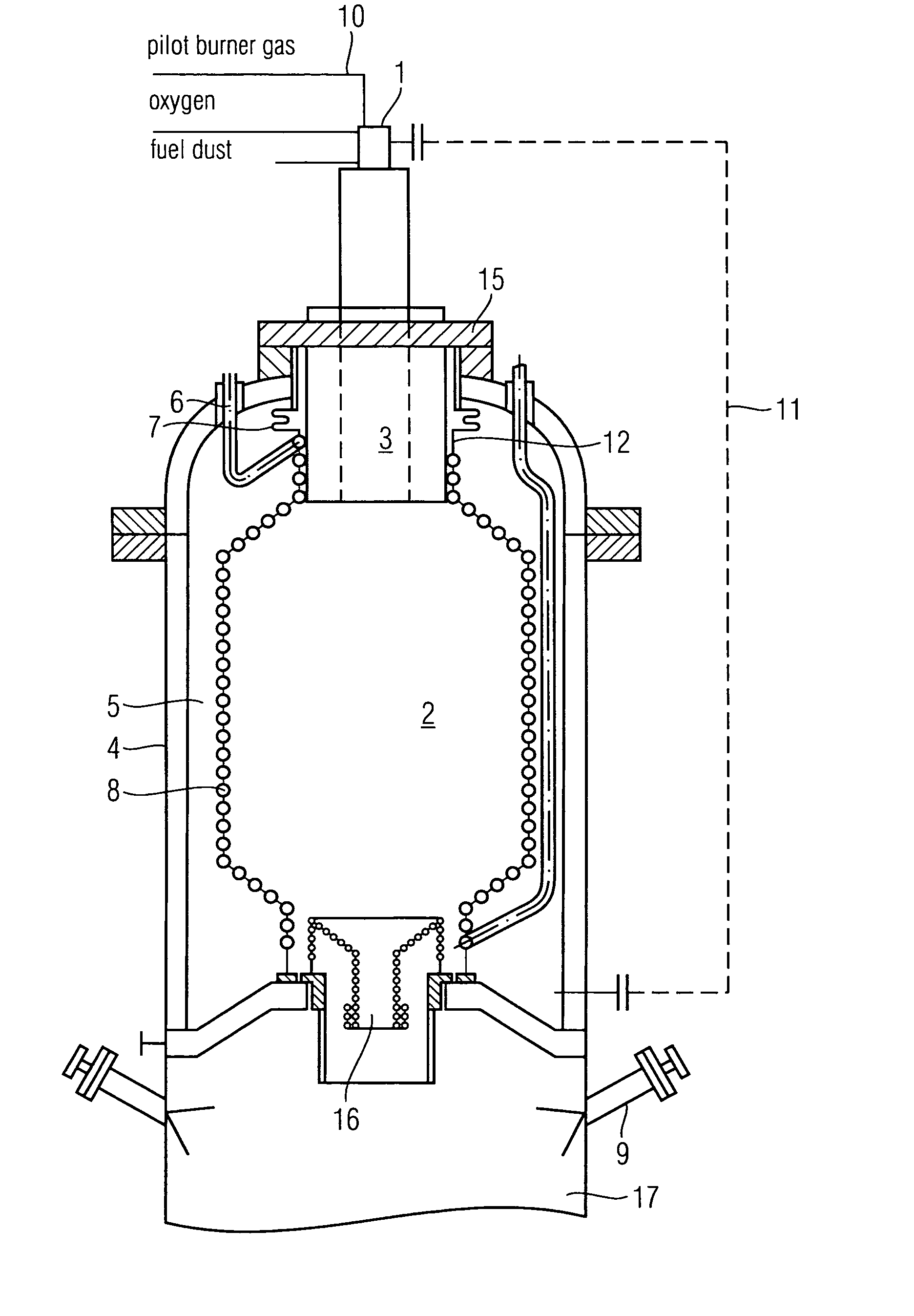
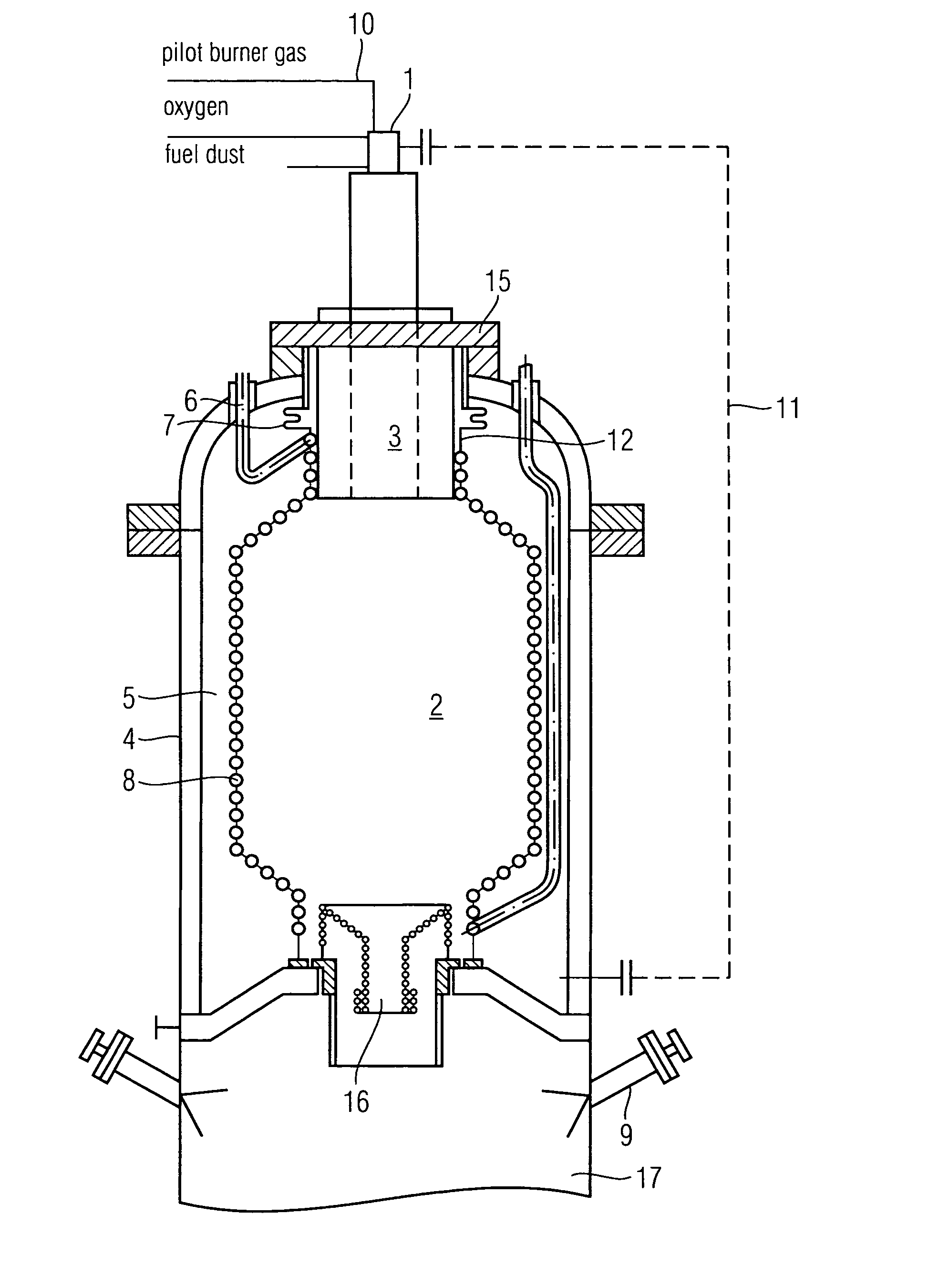
[0011]50 t of coal dust and 35,000 Nm3 of steam, which are converted in the gasification chamber 2 to 75,000 Nm3 of raw syngas at 3 MPa (30 bar) are fed per hour via a gasification burner 1, which also contains a pilot burner, to a gasification reactor as shown in FIG. 1. The gasification burner 1 is arranged in a burner mounting device 3 which is situated near the cover flange 15. The gasification chamber 2 is bounded by a cooling screen 8 fanned by gas-tight, welded cooling tubes. The gasification temperature measured at the outlet device 16 is 1500° C. The hot producer gas along with the liquid slag resulting from the coal ash leaves the gasification chamber 2 via the outlet device 16 and reaches the cooling chamber 17, in which the raw producer gas is cooled to approximately 200° C. by being sprayed with cold water via the nozzles 9 and simultaneously being saturated with steam. The cooled raw gas is then fed to further gas conditioning technologies. An annular gap which has to ...


PUM

PropertyMeasurementUnit
pressureaaaaaaaaaa
temperaturesaaaaaaaaaa

Abstract

In a reactor for the gasification of solid and liquid fuels in the entrained flow at temperatures between 1200 and 1900° C. and pressures between ambient pressure and 10 MPa with an oxidizing agent containing free oxygen, the cooling screen is connected in a gas-tight manner to the pressure shell via a bellows compensator to accommodate linear deformation. Continuous sweeping by gas of the annular gap between pressure shell and cooling screen is unnecessary and backflow by producer gas is prevented.

Description

CROSS REFERENCE TO RELATED APPLICATIONS[0001]This application claims the benefits of German application No. 10 2007 045 321.5 filed Sep. 21, 2007 and is incorporated by reference herein in its entirety.FIELD OF INVENTION[0002]The invention concerns a reactor for the gasification of solid and liquid fuels in the entrained flow, with the features of the claims.BACKGROUND OF THE INVENTION[0003]The invention relates to a reactor for the entrained-flow gasification of different solid and liquid fuels with an oxidizing agent containing free oxygen under normal or increased pressure up to 8 MPa. Here solid fuels are pulverized coal dust from coals of differing ranks, petrol cokes and other pulverizable solids having a calorific value exceeding 7 MJ / Nm3. Liquid fuels are oils or oil-solids or water-solids suspensions, such as coal-water slurries, for example. Autothermal entrained-flow gasification has been known for many years in gas generation technology using solid fuels. In this case th...

Claims


Application Information

Patent Timeline
Patent Type & Authority Patents(United States)
IPC IPC(8): B01J7/00C10J1/207
CPCC01B3/36C10J3/485C10J3/76C10J3/78C10K1/101C10J3/845C10J3/84C01B2203/025C10J2200/09C10J2300/093C10J2300/0933C10J2300/0936
Inventor KIRCHHUBEL, VOLKERSCHINGNITZ, MANFREDTOTH, HEIDRUN
Owner SIEMENS ENERGY GLOBAL GMBH & CO KG
Why Eureka
Try Eureka