Method for encoding and decoding of optical signals

a technology of optical signals and encoding methods, applied in electromagnetic transmission, electrical equipment, transmission, etc., can solve problems such as possible errors in information transfer, multi-level encoding faces severe problems in generating multi-level optical pulses, and the repetition rate of pulses is usually limited, and achieves robust multi-level encoding of optical signals.

Active Publication Date: 2013-07-02
VI SYST GMBH
View PDF1 Cites 2 Cited by
  • Summary
  • Abstract
  • Description
  • Claims
  • Application Information

AI Technical Summary

Benefits of technology

[0010]The present invention refers to a method for robust multi-level encoding of optical signals. The method uses a transmitter that transforms electric signals into optical signals and a receiver capable to transform optical signals into electric signals. The transmitter is capable to generate optical pulses having at least two different durations. The amplitudes of the pulses are preferably close to each other. The transmitter is fast, and the receiver is slow such that the response time of the receiver exceeds at least the shortest of the durations of the optical pulses. Then the receiver effectively integrates the optical signal and generates the electric signal having a larger amplitude when the optical signal has a larger duration. Thus, the method converts the modulation in pulse duration into the modulation in signal amplitude. In different embodiments of the present invention, the transmitter can be realized by a light-emitting diode, superluminescent light-emitting diode, or a diode laser. The receiver can be realized by a p-i-n diode, by a resonant cavity photodetector, or by an avalanche photodiode.

Problems solved by technology

The repetition rate of pulses is usually limited by the high frequency performance of the transmitter and receiver.
However, multilevel encoding faces severe problems regarding generating multi-level optical pulses by a transmitter.
Since the levels of the optical signals I0 and I1 are now hardly distinguishable, this creates possible errors in the information transfer.

Method used


Image

  • Method for encoding and decoding of optical signals
  • Method for encoding and decoding of optical signals
  • Method for encoding and decoding of optical signals

Examples


Embodiment Construction

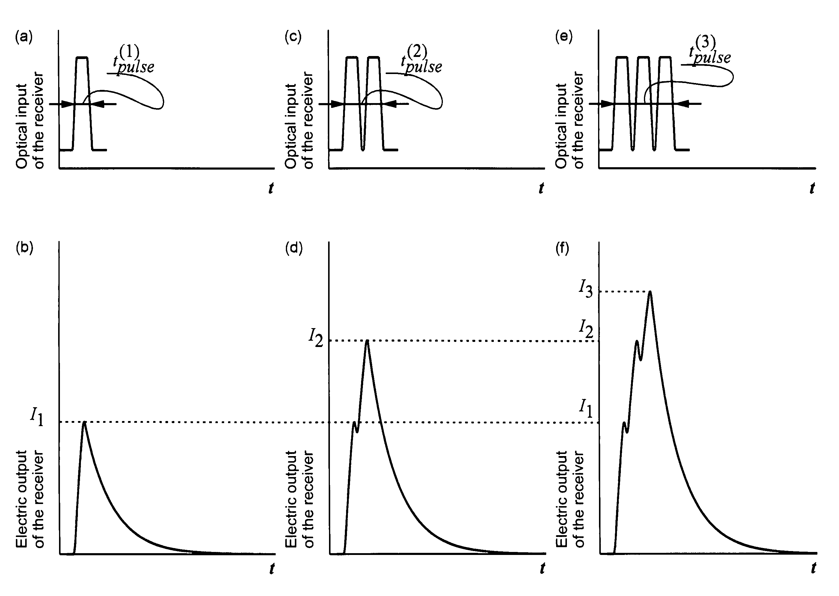
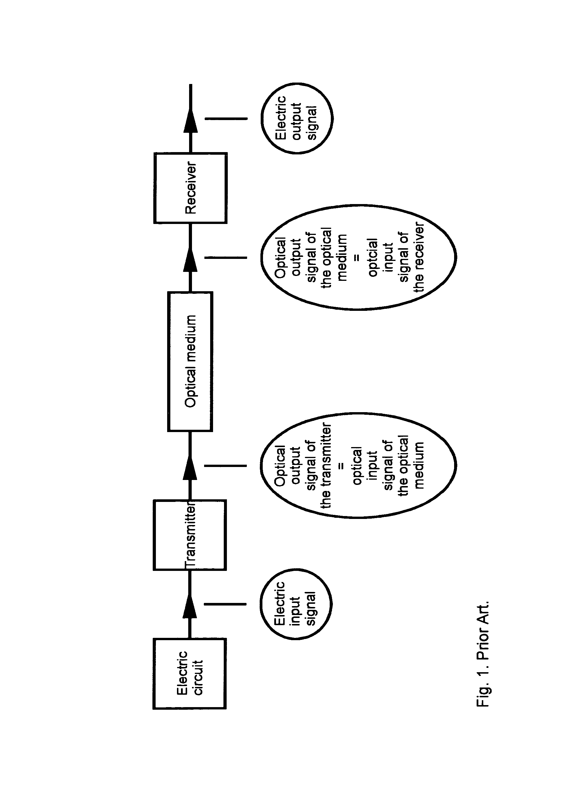
[0034]The present invention teaches using a fast transmitter and a slow receiver. Encoding in the fast transmitter results in generating optical pulses having preferably the same amplitude but different duration. These are “optical output signals of the transmitter”, according to FIG. 1. The same is valid for “optical input signals of the receiver” coming to the receiver. The slow receiver has the characteristic response time preferably longer than the pulse duration. Then it basically integrates the coming optical pulses over time. Then a longer optical pulse will result in an electric pulse having a larger amplitude.

[0035]In one of the embodiments of the present invention, the electric response of the receiver can be written as follows:

[0036]Ielectric⁡(t)=∫-∞t⁢K⁡(t-τ)⁢Ioptical⁡(τ)⁢ⅆτ,(1)

where K(t−τ) is a response function of the receiver characterized by a response time tresponse. In one of practical embodiments, the response function can be written as an exponential,

[0037]K⁡(t-τ)...


PUM


Abstract

The present invention refers to a method for robust multi-level encoding of optical signals. The method uses a transmitter that transforms electric signals into optical signals and a receiver capable to transform optical signals into electric signals. The transmitter is capable to generate optical pulses having at least two different durations. The amplitudes of the pulses are preferably close to each other. The transmitter is fast, and the receiver is slow such that the response time of the receiver exceeds at least the shortest of the durations of the optical pulses. Then the receiver effectively integrates the optical signal and generates the electric signal having a larger amplitude when the optical signal has a larger duration. Thus, the method converts the modulation in pulse duration into the modulation in signal amplitude. In different embodiments of the present invention, the transmitter can be realized by a light-emitting diode, superluminescent light-emitting diode, or a diode laser. The receiver can be realized by a p-i-n diode, by a resonant cavity photodetector, or by an avalanche photodiode.

Description

REFERENCE TO RELATED APPLICATIONS[0001]This application claims an invention which was disclosed in Provisional Application No. 61 / 272,476, filed Sep. 28, 2009, entitled “Method for Encoding of Optical Signals”. The benefit under 35 USC §119(e) of the United States provisional application is hereby claimed, and the aforementioned application is hereby incorporated herein by reference.BACKGROUND OF THE INVENTION[0002]1. Field of the Invention[0003]The invention pertains to the field of encoding and decoding of optical signals and to the field of semiconductor optoelectronic devices.[0004]2. Description of Related Art[0005]The rate of information transfer increases many-fold each decade. A permanent need in a speed increase and reducing power consumption leads to the fact that the application field of optoelectronic devices used in the information transfer is gradually expanding. FIG. 1 shows schematically a general scheme of the information transfer using optoelectronic components. An...

Claims


Application Information

Patent Timeline
Patent Type & Authority Patents(United States)
CPCH04B10/524H04B10/66H04B2210/517
Inventor LEDENTSOV, NIKOLAISHCHUKIN, VITALY
Owner VI SYST GMBH
Why Eureka
Try Eureka