Nebuliser

a technology of nebuliser and fluid, which is applied in the direction of respirator, single-unit apparatus, separation process, etc., can solve the problems of difficult production, small manufacturing tolerance, and thick wall of capillaries, and achieves simple and inexpensive production and great stability.

Active Publication Date: 2013-07-09
BOEHRINGER INGELHEIM INT GMBH
View PDF20 Cites 24 Cited by
  • Summary
  • Abstract
  • Description
  • Claims
  • Application Information

AI Technical Summary

Benefits of technology

[0008]A primary object of the present invention is to provide a nebuliser having a conveying tube and a method of producing a capillary, wherein the conveying tube or the capillary is simple and inexpensive to produce with a thick-walled construction, and particularly, with a smooth inner wall, while having great stability.
[0009]This aim is achieved by a nebuliser and method according to one aspect of the present invention by making a thick-walled capillary or a conveying tube of a nebuliser preferably, formed therefrom with a double-walled construction. This enables the object to be produced more easily and hence more cheaply than in the prior art, with low manufacturing tolerances. In particular, it is possible to achieve a smoother inner surface. The double-walled construction, in fact, makes it possible to use standard commercial thin-walled capillaries, so that the large number of forming steps that were previously required can be eliminated or reduced.
[0010]Particularly, preferably, an inner tube is concentrically installed in an outer tube to form the conveying tube or the thick-walled capillary. The tubes are then constructed, in particular, as thin-walled capillaries which can be obtained cheaply and to a high quality.

Problems solved by technology

The conveying tube is therefore very difficult and complex to produce.
Capillaries with a thick wall and small manufacturing tolerances are, however, very difficult to produce and often have undesirably rough inner walls.

Method used


Image

  • Nebuliser
  • Nebuliser
  • Nebuliser

Examples


first embodiment

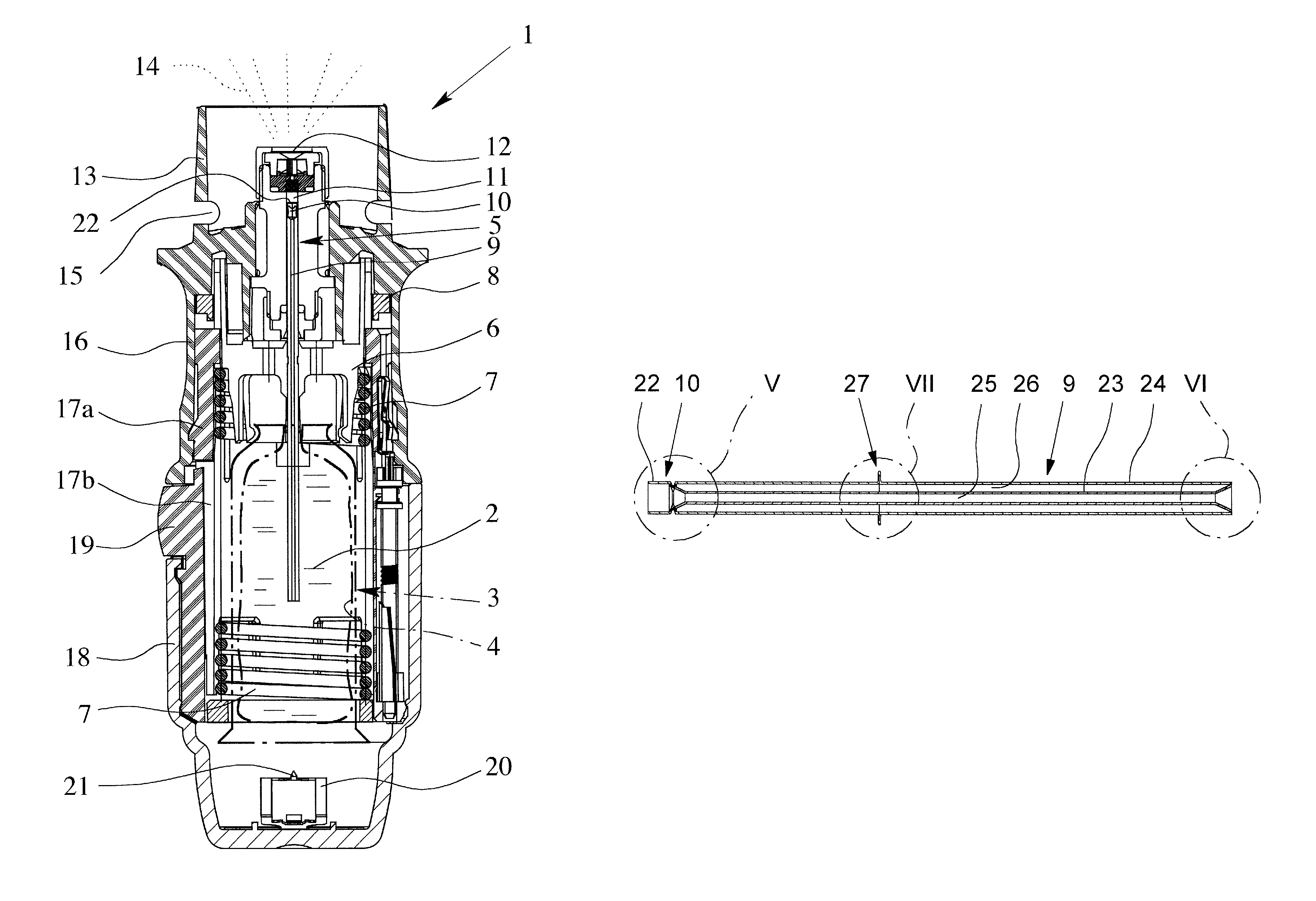
[0045]FIG. 3 shows, in schematic section, the container 3 and part of the associated proposed nebuliser 1 according to a The conveying tube 9 comprises an inner tube 23 and an outer tube 24, which are preferably, arranged concentrically to one another and / or formed as thin walled, in particular standard commercial capillaries.

[0046]The conveying tube 9 is thus double walled and preferably, multi-part in construction and especially is in the form of a thick walled but preferably, not massive capillary. The double walled and particularly, multi-part construction makes it possible in particular to manufacture the conveying tube 9 particularly, cheaply and / or precisely, most preferably, with a smooth and / or round inner wall or contour.

[0047]The inner tube 23 forms a conveying channel 25 on the inside. The annular space 26 between the inner tube 23 and the outer tube 24 preferably, forms a venting channel in the first embodiment. Alternatively, the annular chamber 26 may also preferably...

second embodiment

[0063]In the second embodiment, the valve seat 33 is, preferably, formed by a concentric region or section of the outer tube 24, particularly, an encircling narrowing or bead 34. However, other constructive solutions are also possible.

[0064]The inner tube 23 preferably, has a radially widening, particularly, at least partially conical connecting portion 35 which, in this case, is formed at the end of the inner tube 23 and expands, in particular, at least substantially to the inner diameter of the outer tube 24. The two tubes 23, 24 are joined together by the connecting portion 35, particularly, by welding, gluing or the like. For example, it is possible to carry out welding through the outer wall of the outer tube 24 in a substantially radial direction.

[0065]Thus, the inner tube 23 extends at least substantially as far as the valve seat 33 or up to the preferably, radial narrowing or bead 34, thus minimising the volume through which the fluid 2 can flow in the conveying tube 9 or co...

fourth embodiment

[0076]FIG. 11 shows, in an enlarged detail from FIG. 8, the retaining region 27 of the conveying tube 9. Instead of a projection, the retaining region 27, in this fourth embodiment, preferably, has a radial indentation or recess 37 particularly, an annual groove, a step, a bead or the like, several of which may be provided one behind the other and in particular a corrugated outer contour may be formed by the retaining region 27.

[0077]According to a particularly, preferred aspect, the outer tube 24 at the retaining region 27 is deformed axially inwards such that it bears on the inner tube 23. If necessary, the outer tube 24 in this contact region may also be fixedly connected to the inner tube 23, e.g., by welding or adhesive bonding. This can contribute to the overall stability of the conveying tube 9. However, it is also possible for a radial spacing to be maintained between the outer tube 24 and the inner tube 23 at the retaining region 27.

[0078]FIG. 12 shows a fourth embodiment o...


PUM


Abstract

A nebulizer for a fluid which has a conveying tube for conveying fluid and a method for producing a thick-walled capillary. The conveying tube or the capillary is of multipart and / or double-walled construction, and in particular, is made up of a number of parts, such as an inner tube and an outer tube. This construction allows the device to be manufactured more easily and cheaply, in particular, when the inner diameters are very small.

Description

BACKGROUND OF THE INVENTION[0001]1. Field of the Invention[0002]The present invention relates to a nebuliser for a fluid having a conveying tube for conveying the fluid, wherein in particular the conveying tubeis constructed as a thick-walled capillary and a method of producing a thick-walled capillary.[0003]2. Description of Related Art[0004]A nebuliser available under the trademark RESPIMAT® in the form of an inhaler is known, and is illustrated in its basic form in International Patent Application Publication WO 91 / 14468 A1 (U.S. Pat. No. 5,662,271) and in a specific configuration in International Patent Application Publication WO 97 / 12687 A1 (U.S. Pat. Nos. 6,918,547 and 6,726,124) as well as in FIGS. 1 & 2 of the accompanying drawings of this application. The nebuliser has a conveyor device with a conveying tube for conveying and atomising the fluid. The conveying tube is constructed, in particular, as a thick-walled massive capillary, as shown in FIG. 3b of WO 97 / 12687 A1. The...

Claims


Application Information

Patent Timeline
Patent Type & Authority Patents(United States)
IPC IPC(8): A61M11/00A61M15/00A61M16/00
CPCB05B11/0016B05B11/0054B05B11/3091B05B11/3001B05B11/0044B05B11/1001B05B11/1091B05B11/00B05B7/02
Inventor HAUSMANN, MATTHIASHEGEMANN, UWE
Owner BOEHRINGER INGELHEIM INT GMBH
Why Eureka
Try Eureka