Cabin heating control system

a control system and cabin technology, applied in electric control, machines/engines, transportation and packaging, etc., can solve the problems of reducing fuel economy, adding additional system complexity and cost, and insufficient heat provided to the cabin during extended idle conditions, so as to increase the coolant flow, prolong the idle period, and prolong the idle period

Active Publication Date: 2013-07-09
FORD GLOBAL TECH LLC
View PDF32 Cites 4 Cited by
  • Summary
  • Abstract
  • Description
  • Claims
  • Application Information

AI Technical Summary

Benefits of technology

[0002]One approach provides an additional pump to provide the additional flow so that such low flow conditions may be avoided. However, this may add additional system complexity and cost. The inventors herein have recognized an alternative approach may be used that increases engine idle speed during cold ambient temperature to provide the increased coolant flow to the rear cabin heating system. However, such an approach can decrease fuel economy, and increase concerns with high idle speed operation noticed by the customer.
[0004]In this way, during normal driving conditions, while a customer drives down the road, the engine speed resulting from the drive cycle is typically high enough to provide coolant flow to the rear heater without the auxiliary pump. Then, when the vehicles comes to a stop there is typically enough thermal inertia in the heater core to provide heat for a couple of minutes, so the coolant flow can be delayed and fuel economy maintained. Yet, during those conditions of an extended low flow (e.g., extended idle), the engine speed can be increased to increase coolant flow until vehicle driving is again resumed. Thus, improved heating can be obtained while sacrificing fuel economy only during limited conditions, and while addressing vehicle drivability and high idle speed warranty concerns.

Problems solved by technology

In some cases, during lower coolant flow (e.g., idle) conditions, the coolant flow to certain areas (e.g., to the rear cabin area of the vehicle) may be too low, and thus insufficient heat may be provided to the cabin during an extended idle condition.
However, this may add additional system complexity and cost.
However, such an approach can decrease fuel economy, and increase concerns with high idle speed operation noticed by the customer.

Method used


Image

  • Cabin heating control system
  • Cabin heating control system
  • Cabin heating control system

Examples


Embodiment Construction

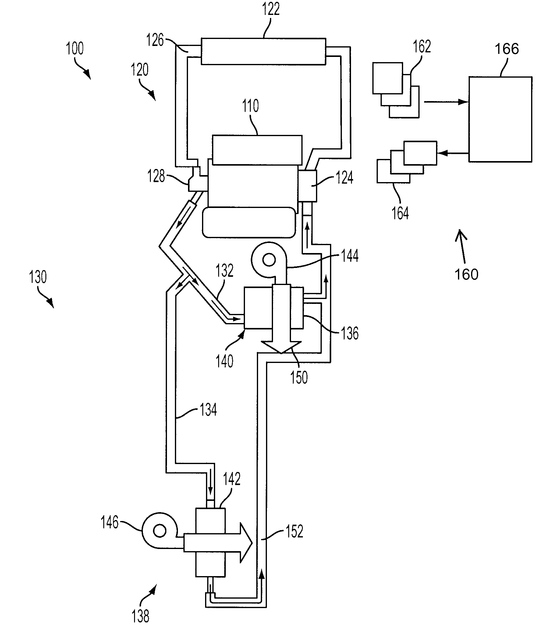
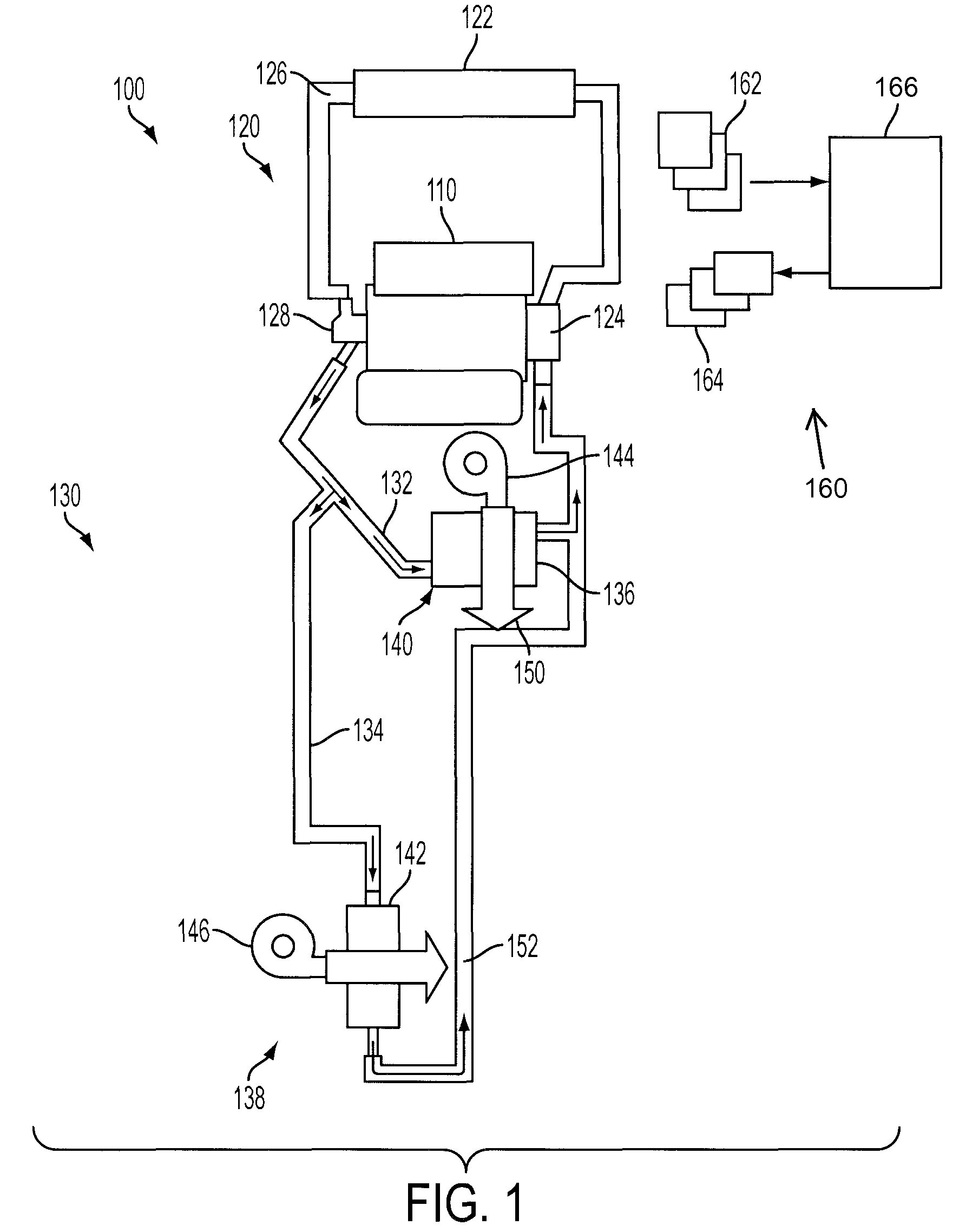
[0009]FIG. 1 shows an example vehicle cabin heating system 100. The system utilizes engine waste heat absorbed by the engine cooling system to provide cabin heating to a plurality of heat exchangers, which can be referred to herein as a multi-heating unit system, and in this particular example, a dual heating system.

[0010]In particular, FIG. 1 shows an engine 110 having a cooling system 120 for circulating engine coolant from the engine to a radiator 122 via a water pump 124, and back to the engine via a coolant line 126. The water pump may be coupled on the engine front end accessory drive (FEAD), and rotated proportionally to engine speed via belt, chain, etc. Specifically, the water pump 124 circulates coolant through passages in the engine block, head, etc., to absorb engine heat, which is than transferred via the radiator 122 to ambient air. In the example where pump 124 is a centrifugal pump, the pressure (and resulting flow) produced may be proportional to the shaft speed, wh...


PUM


Abstract

A system described is for providing improved cabin heating. The system may include a vehicle cabin heating system having a first and second heating system receiving coolant flow from the engine; and a control system for operating the engine at a first engine idle speed upon entering idle speed control operation from previous drive operation, maintaining said first idle speed for a duration, and then increasing engine speed to increase coolant flow to the second heating system during cold ambient conditions when the second heater system is in operation.

Description

BACKGROUND AND SUMMARY[0001]Vehicle climate control systems, or heating systems, may use coolant to provide cabin heat, and may further provide such coolant flow to multiple locations of the cabin, such as the, front, rear, left side, right side, etc. In some cases, during lower coolant flow (e.g., idle) conditions, the coolant flow to certain areas (e.g., to the rear cabin area of the vehicle) may be too low, and thus insufficient heat may be provided to the cabin during an extended idle condition.[0002]One approach provides an additional pump to provide the additional flow so that such low flow conditions may be avoided. However, this may add additional system complexity and cost. The inventors herein have recognized an alternative approach may be used that increases engine idle speed during cold ambient temperature to provide the increased coolant flow to the rear cabin heating system. However, such an approach can decrease fuel economy, and increase concerns with high idle speed...

Claims


Application Information

Patent Timeline
Patent Type & Authority Patents(United States)
IPC IPC(8): B60H1/00B60H1/02B60H1/32
CPCB60H1/00885B60H1/06
Inventor DAME, ANDREW CLEMENTJACOBSEN, BRENTGRANT, ROBERT MICHAELLEISENRING, KEN CARL
Owner FORD GLOBAL TECH LLC
Why Eureka
Try Eureka