Heat exchanger and fluid reservoir

a technology of fluid reservoir and heat exchanger, which is applied in the direction of indirect heat exchangers, lighting and heating apparatus, laminated elements, etc., can solve the problems of poor thermal exchange efficiency, large unswept or “dead” volumes, poor tasting liquid and/or microbial contamination of the liquid, etc., and achieve high thermal exchange efficiency.

Inactive Publication Date: 2006-02-02
3M INNOVATIVE PROPERTIES CO
View PDF12 Cites 34 Cited by
  • Summary
  • Abstract
  • Description
  • Claims
  • Application Information

AI Technical Summary

Benefits of technology

[0005] Improved fluid reservoirs of the present disclosure comprise structure to eliminate low flow conditions so as to have little or no un-swept or dead volumes within the fluid reservoir. In addition, the improved fluid reservoirs of the present disclosure can provide for relatively high efficient thermal exchange so as to provide a desirable chilled fluid product for use and consumption. In some representative, presently preferred, embodiments, improved fluid reservoirs can comprise a serpentine fluid flow passage having a cross-section configured such that the fluid flow within the flow passage sweeps the entire cross-sectional volume of the flow passage without leaving significant amounts of dead or un-swept volume therein. The cross-sectional shape of the flow passage can be configured to have a larger heat transfer surface than known prior coiled tube reservoirs, which can allow the fluid to be chilled through placement of improved fluid reservoir in proximity to a cooling environment such as, for example, within or in proximity to a refrigeration or freezer compartment in a refrigerator.
[0007] In one aspect, the fluid reservoirs of the present disclosure can have a thin profile for convenient placement along and / or within the walls / floor / ceiling and / or mullions of an appliance. This thin profile is consistent both with very good thermal exchange and flow with little or no dead volume. The fluid reservoir can be placed in thermal contact with the cooling compartment. Due to the thermal contact, liquid delivered from the fluid reservoir can be chilled, and the configuration provides for good chilling efficiency. Fluid Reservoir design of the present disclosure combine some of the advantages of a coil tube fluid reservoir with those of a tank-style fluid reservoir, while eliminating many of the drawbacks associated with either the coil tube fluid reservoir or the tank-style fluid reservoir.
[0013] In some presently contemplated representative embodiments, the fluid reservoirs of the present disclosure can operatively interface with an appropriate dispenser. Generally, operation of the dispenser can be triggered by a user requesting a desired amount of fluid such as, for example, water. In some presently contemplated representative embodiments, water can be dispensed through a dispenser in an appliance door such as, for example, a refrigerator door. In some alternative representative embodiments, the dispenser can be located internal to an appliance such as, for example, within a refrigerated compartment of a refrigerator, as described further in copending U.S. Provisional Application No. 60 / 537,781 to Meuleners et al., entitled “WATER FILTER AND DISPENSER ASSEMBLY,” the disclosure of which is herein incorporated by reference to the extent not inconsistent with the present disclosure. Placement and orientation of the fluid reservoirs of the present disclosure within an appliance can allow for practical considerations during installation as well as providing effective venting of air that may be contained within a fluid filtration system and / or the fluid reservoir itself prior to connection to a fluid supply. Fluid reservoirs of the present disclosure can have flow passage cross-sections selected to be small enough as to allow air to be pushed out of the flow passage due to the surface tension of the fluid regardless of the fluid reservoir orientation.

Problems solved by technology

One disadvantage of prior known tank-style fluid reservoirs can be the creation of significant un-swept or “dead” volumes with little or no flow.
These dead volumes can lead to stagnant flow conditions that can result in stale, poor tasting liquid and / or microbial contamination of the liquid.
One known disadvantage of prior coiled tube tanks is that they can have a relatively poor thermal exchange efficiency due to the small portion of the tank surface that is accessible to thermal exchange when mounted in certain configurations.
Coil tube fluid reservoirs can also be difficult to manufacture, require large amounts of polymer or other material to manufacture, and can result in bad tasting water due to fluid contact with the large surface area associated with prior known coil tube fluid reservoir materials.
Further, prior coil tube fluid reservoirs often exhibit significant internal friction that can result in large pressure drops during operation.

Method used


Image

  • Heat exchanger and fluid reservoir
  • Heat exchanger and fluid reservoir
  • Heat exchanger and fluid reservoir

Examples


Embodiment Construction

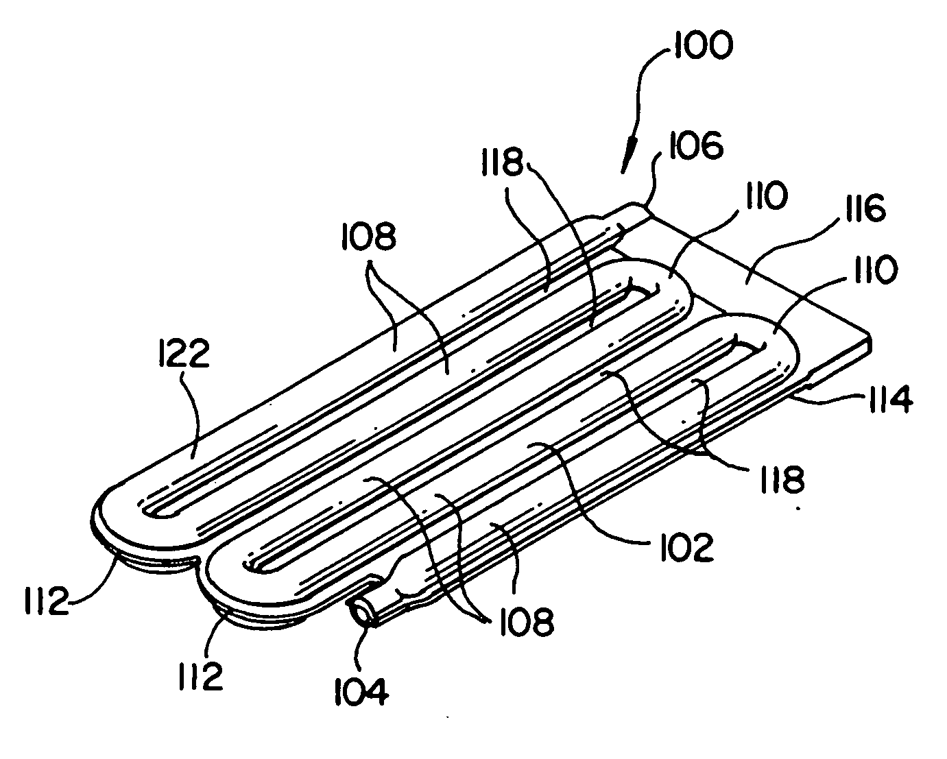
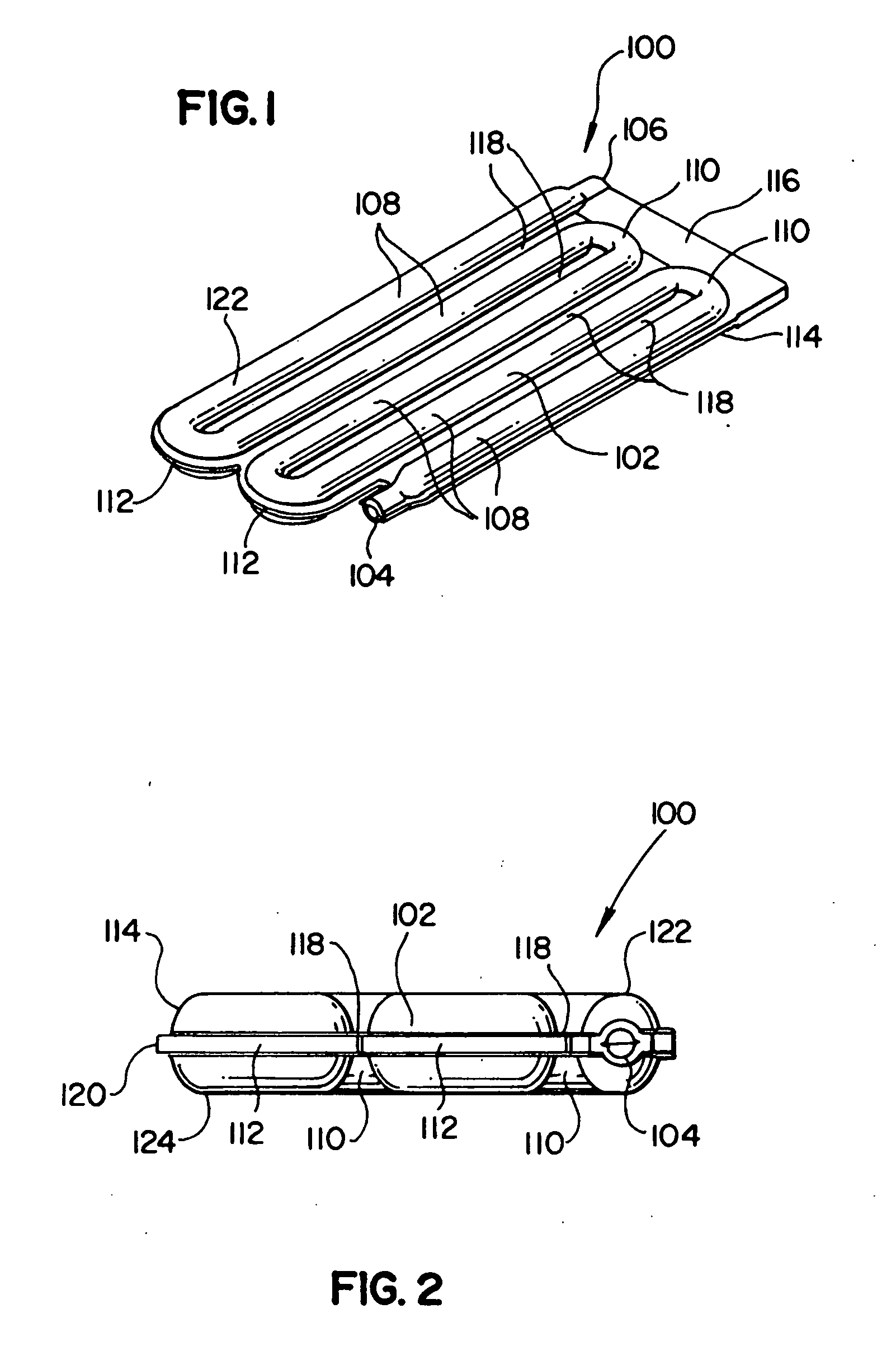
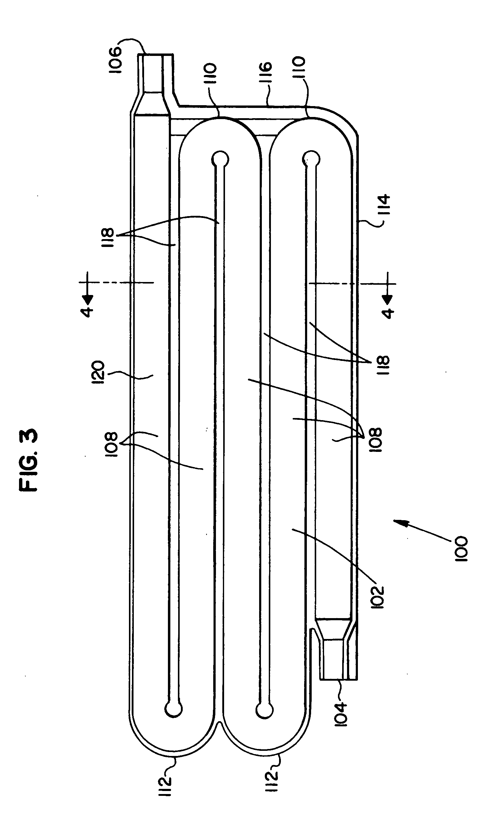
[0042] Improved fluid reservoirs described herein combine features of coiled tubes and tank fluid reservoirs to achieve desirable features of both types while exhibiting fewer drawbacks that are representative of each. New, improved, desirable processing approaches have made these previously commercially impractical fluid reservoirs practical on a commercial scale. In some presently preferred representative embodiments, the fluid reservoirs are designed to have flow that provides first in-first out flow without low flow or dead volume areas that can lead to stale liquid. At the same time, some presently preferred representative embodiments of fluid reservoirs can have a larger flow passage cross section than conventional coiled tubes so that less material is used and the pressure drop is less for a given tank volume. In some representative embodiments, the fluid reservoirs are in the form of a monolithic structure with a curved flow path and adjacent flow channels separated with a s...


PUM

PropertyMeasurementUnit
Reynolds numberaaaaaaaaaa

Abstract

Improved fluid reservoir designs providing for little or no dead volume or un-swept volume while providing efficient heat exchange are disclosed. Representative fluid reservoirs can have a serpentine flow passage with a cross-section selected such that fluid flow sweeps the entire cross-sectional volume while reducing or eliminating dead volume. The cross-sectional shape of the flow passage can be selected to have a larger surface contact with the cooling environment relative to circular cross-sections. The fluid reservoirs can be molded from two sheets of polymer material that are joined to form the fluid reservoir. Alternatively, the fluid reservoir can be formed from flexible polymer materials that are bonded along seams to demarcate a flow channel. Fluid reservoirs can be located either upstream or downstream of a filtering system to provide chilled filtered liquid. Fluid reservoirs can be associated with an appliance, such as a refrigerator. Methods of fabricating the fluid reservoirs are also disclosed.

Description

RELATED APPLICATIONS [0001] The present application is a continuation-in-part of and claims priority under 35 U.S.C. § 119(e) to U.S. Provisional Applications Nos. 60 / 591,646, filed Jul. 28, 2004, entitled, “HEAT EXCHANGER AND LIQUID RESERVOIR,” 60 / 604,952, filed Aug. 27, 2004, entitled, “HEAT EXCHANGER AND LIQUID RESERVOIR,” and 60 / 634,621, filed Dec. 9, 2004, entitled, “HEAT EXCHANGER AND LIQUID RESERVOIR,” all three of the aforementioned applications being incorporated herein by reference to the extent not inconsistent with the present disclosure.BACKGROUND OF THE DISCLOSURE [0002] The present disclosure relates generally to the field of fluid reservoirs and more particularly, to use of the fluid reservoirs in appliances having water systems. Fluid reservoirs of the present disclosure can provide for first-in / first-out flow providing beneficial performance characteristics such as, for example, prevention of stagnant flow and improved heat transfer for providing chilled water. [00...

Claims


Application Information

Patent Timeline
Patent Type & Authority Applications(United States)
IPC IPC(8): F28F1/10
CPCB29C65/02B29C65/04B29C65/08B29C65/18B29C65/48B29C66/54B29C66/545F28D1/035F28F3/12F28F21/065F28F2275/025F28F2275/06B29C66/53263B29L2031/18B29C66/71B29C66/1122B29C66/723B29C66/1312B29K2077/00B29K2075/00B29K2067/00B29K2025/06B29K2023/12B29K2023/0691B29K2023/06B29K2023/00F28F21/06F28D1/03
Inventor FRITZE, KARLMEULENERS, WILLIAM J.
Owner 3M INNOVATIVE PROPERTIES CO
Why Eureka
Try Eureka