Anti-roll system for vehicles

a technology for vehicles and wheels, applied in the direction of interconnection systems, resilient suspensions, vehicle springs, etc., can solve the problems of affecting the safety of the vehicle while the vehicle turns, affecting the stability of the vehicle, and affecting the safety of the vehicle, etc., to achieve the effect of reducing the amount of roll of the vehicle, increasing the rigidity of the roll, and improving the driving/turning stability of the vehicl

Active Publication Date: 2013-07-09
HYUNDAI MOTOR CO LTD
View PDF8 Cites 0 Cited by
  • Summary
  • Abstract
  • Description
  • Claims
  • Application Information

AI Technical Summary

Benefits of technology

[0019]Various aspects of the present invention are directed to providing an anti-roll device for a vehicle having advantages of using a streamlines plate spring and an assistant spring to suppress a large amount of roll of a vehicle and increase roll rigidity along with the size of a lateral load that is input to improve driving / turning stability of a vehicle.
[0020]Also, Various aspects of the present invention are directed to providing an anti-roll device for a vehicle having advantages of applying a streamlined plate spring such that the energy absorption capacity is improved, the length of a front / rear direction thereof is reduced to eliminate interference, there is a merit in a layout aspect, and a load input angle with a pushrod is reduced to improve load transferring efficiency.
[0021]Further, Various aspects of the present invention are directed to providing an anti-roll device for a vehicle having advantages of directly engaging a pushrod with a plate spring such that the number of engagement components is reduced to be simple.
[0030]An exemplary embodiment of the present invention uses the “S” type streamlined plate spring and an assistant spring such that roll rigidity is non-linearly increased depending on the size of a lateral load that is input and suppresses a roll of a vehicle against a large amount of roll to secure turning and driving stability.
[0031]Further, a streamlined plate spring is applied to improve energy absorption capacity and to reduce the length of a front / rear direction thereof such that interference between components is eliminated and there is a merit in a layout aspect.
[0032]A load input angle that is transferred from a push rod and a tire is reduced to improve load transferring efficiency, and a push rod and a plate spring are directly engaged to reduce the number of engagement components to be simple.

Problems solved by technology

Particularly, the rolling adversely affects the safety while the vehicle turns, and a stabilizer bar is applied to reduce the side effect of the rolling in a conventional art.
However, a conventional stabilizer bar generates friction with a mounting bush that is mounted in a vehicle body to cause ride discomfort, and the roll rigidity of the stabilizer bar is uniform regardless of the size of a lateral load (i.e., roll angle), and therefore the stability of the vehicle cannot be guaranteed,
Also, there is a drawback that lubrication of rubber of a mounting bush is transformed or worn out to generate noise.
However, in a conventional anti-roll device for a vehicle as described above, the front / rear length of the plate spring 107 is long to generate interference with a vehicle body (e.g., TW: tire wall) or an adjacent component (e.g., TK; fuel tank) and there is a drawback in a layout aspect.
Also, because the entire length of the plate spring 107 cannot be increased because of the layout, it is disadvantageous in terms of energy absorption capacity, and because a load input angle that is transferred from a tire (T) and the push rod 109 is large, there is a drawback that load transferring efficiency is low.
Also, there is a drawback that a bracket (B) for engaging the push rod 109 with the plate spring 107 needs to be prepared for an assemble angle.

Method used


Image

  • Anti-roll system for vehicles
  • Anti-roll system for vehicles
  • Anti-roll system for vehicles

Examples


Embodiment Construction

[0042]Reference will now be made in detail to various embodiments of the present invention(s), examples of which are illustrated in the accompanying drawings and described below. While the invention(s) will be described in conjunction with exemplary embodiments, it will be understood that the present description is not intended to limit the invention(s) to those exemplary embodiments. On the contrary, the invention(s) is / are intended to cover not only the exemplary embodiments, but also various alternatives, modifications, equivalents and other embodiments, which may be included within the spirit and scope of the invention as defined by the appended claims.

[0043]Hereinafter, an exemplary embodiment of the present invention will be described in detail with reference to the accompanying drawings.

[0044]However, parts that are not related thereto will be omitted so as to clearly describe an exemplary embodiment of the present invention.

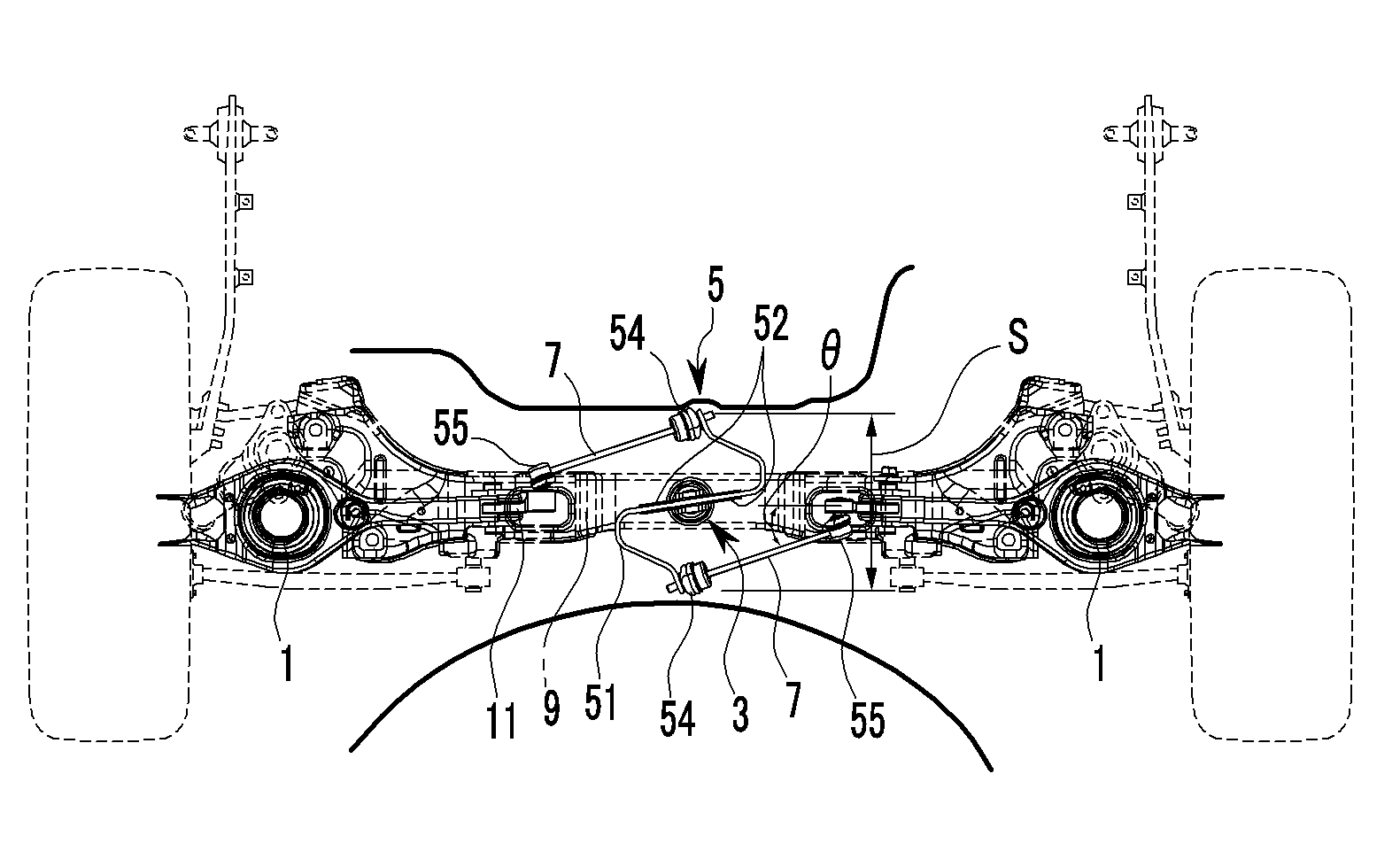
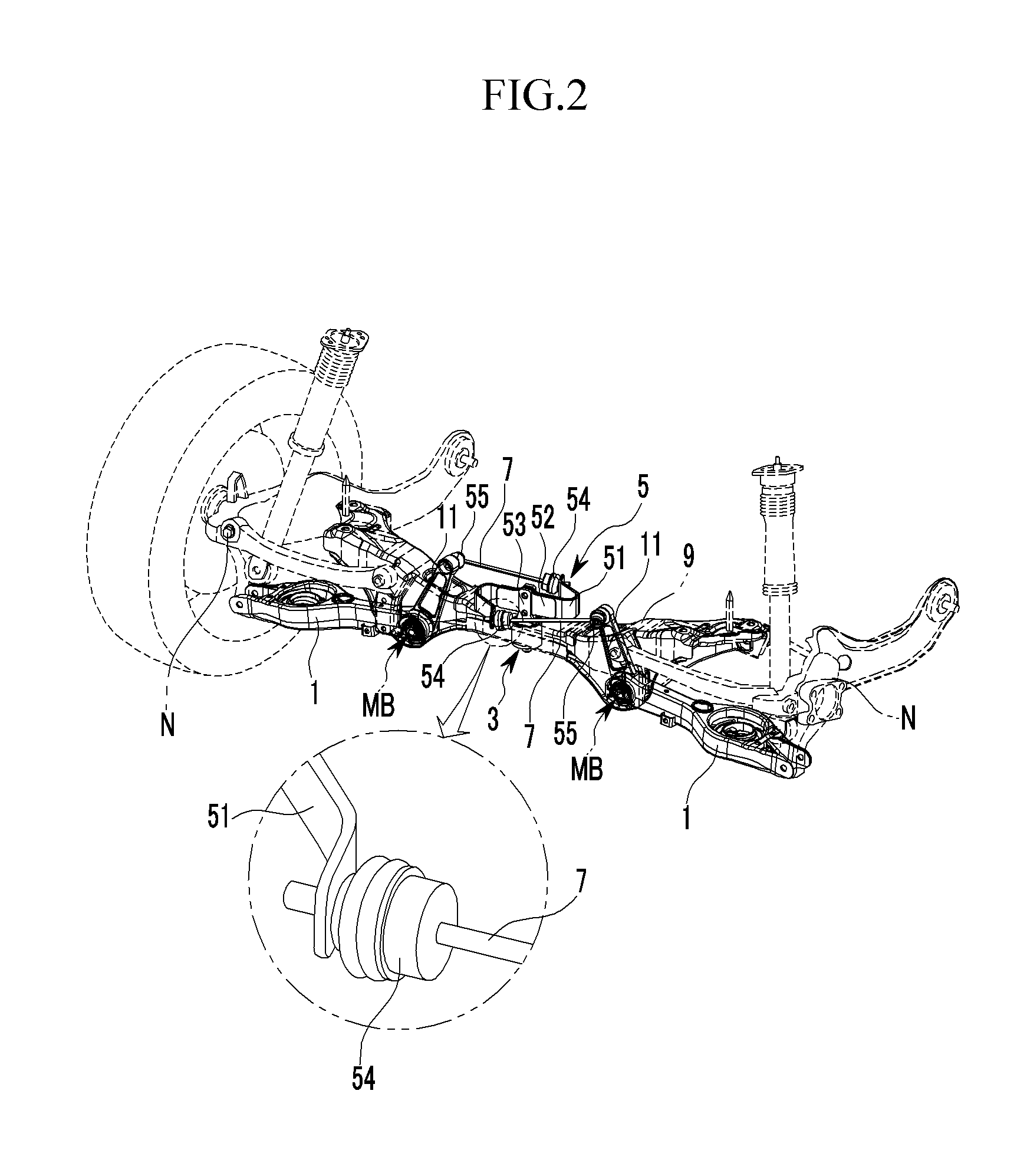
[0045]FIG. 2 is a perspective view of an anti-roll ...


PUM


Abstract

An anti-roll device for a vehicle may include a lower arm disposed at both sides of a sub-frame, a rotation mounter formed at a middle portion of the sub-frame, a spring unit of which the middle portion is rotatably disposed at the rotation mounter, and a push rod connected to both sides of the spring unit and the lower arm, wherein the spring unit includes a plate spring of which both end portions are bent in opposite directions, an engagement portion having an engagement hole in the middle portion thereof is formed, and a bolt hole is formed at both ends thereof, an assistant spring that is disposed at both sides of the engagement portion and an assemble hole is formed in the middle portion corresponding to the engagement hole, and an engagement yoke engaged with the plate spring and the assistant spring and disposed on the rotation mounter.

Description

CROSS-REFERENCE TO RELATED APPLICATION[0001]The present application claims priority to Korean Patent Application No. 10-2011-0132227 filed in the Korean Intellectual Property Office on Dec. 9, 2011, the entire contents of which is incorporated herein for all purposes by this reference.BACKGROUND OF THE INVENTION[0002]1. Field of the Invention[0003]The present invention relates to an anti-roll device for a vehicle. More particularly, the present invention relates to an anti-roll device for a vehicle (Anti-Roll System) that uses a streamlined plate spring and an assistant spring to improve turning stability of a vehicle and to non-linearly increase roll rigidity depending on the size of a lateral load that is input.[0004]2. Description of Related Art[0005]Generally, a suspension system of a vehicle connects an axle with a vehicle body, and prevents vibration or impact that is transferred from the road from being transferred to the vehicle body while driving to enhance ride comfort.[00...

Claims


Application Information

Patent Timeline
Patent Type & Authority Patents(United States)
IPC IPC(8): B60G21/055
CPCB60G11/34B60G21/05B60G2200/182B60G2202/114B60G2202/117B60G2204/121B60G2206/428B60G2204/421B60G2204/422B60G2204/82B60G2204/8302B60G2206/427B60G2204/418
Inventor LEE, UN KOOJANG, SUNG BAEKO, DAESIKKIM, JONG MIN
Owner HYUNDAI MOTOR CO LTD
Why Eureka
Try Eureka