Method and system for providing a read sensor in a magnetic recording transducer using focused ion beam scan polishing

a technology of magnetic recording transducer and read sensor, which is applied in the manufacture of flux-sensitive heads, instruments, record information storage, etc., can solve the problems of underlying metal layer corrosion and typical difficulty in controlling the cmps performed

Inactive Publication Date: 2013-07-09
WESTERN DIGITAL TECH INC
View PDF11 Cites 147 Cited by
  • Summary
  • Abstract
  • Description
  • Claims
  • Application Information

AI Technical Summary

Benefits of technology

[0011]FIG. 1 is a flow chart depicting a conventional method for fabricating a read sensor for magnetic

Problems solved by technology

It may also be typically difficult to control the CMPs performed in steps 20 and 24.
Further, the slurry used for the CMPs perform

Method used


Image

  • Method and system for providing a read sensor in a magnetic recording transducer using focused ion beam scan polishing
  • Method and system for providing a read sensor in a magnetic recording transducer using focused ion beam scan polishing
  • Method and system for providing a read sensor in a magnetic recording transducer using focused ion beam scan polishing

Examples


Embodiment Construction

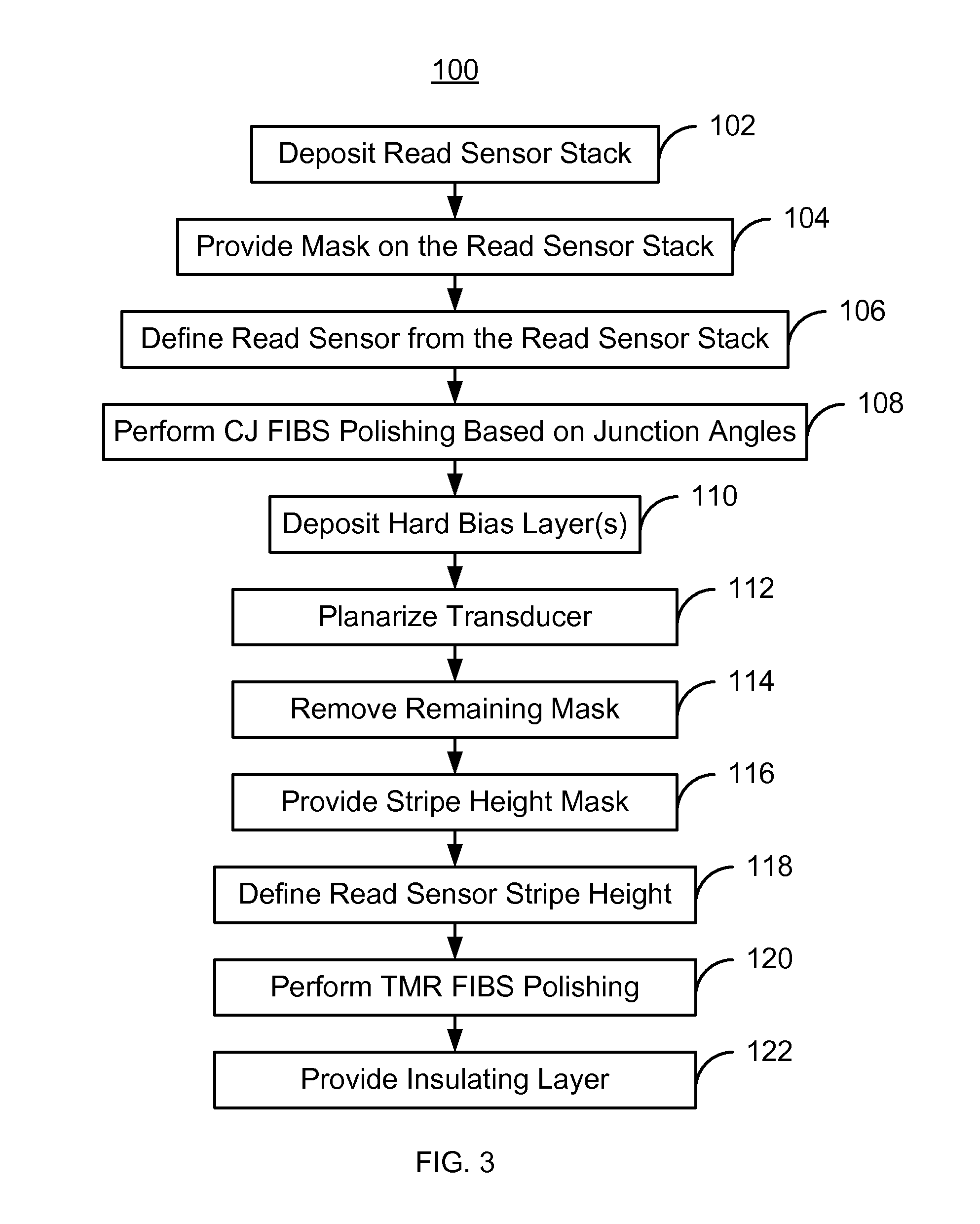
[0020]FIG. 3 is an exemplary embodiment of a method 100 for providing magnetic recording transducer. For simplicity, some steps may be omitted. The method 100 is also described in the context of providing a single recording transducer. However, the method 100 may be used to fabricate multiple transducers at substantially the same time. The method 100 is also described in the context of particular layers. A particular layer may include multiple materials and / or multiple sub-layers. The method 100 also may start after formation of other portions of the magnetic recording transducer. For example, the method 100 may start after layers underlying the magnetoresistive sensor, such as a tunneling magnetoresistive (TMR) sensor have been fabricated.

[0021]A read sensor stack is deposited on the substrate, via step 102. The magnetoresistive layers may include a pinning layer, a pinned layer, a nonmagnetic spacer layer, and a free layer. In addition, seed and / or capping layers may be used. The ...


PUM

PropertyMeasurementUnit
Thicknessaaaaaaaaaa
Angleaaaaaaaaaa
Heightaaaaaaaaaa

Abstract

A read sensor for a read transducer is fabricated. The read transducer has field and device regions. A read sensor stack is deposited. A mask covering part of the stack corresponding to the read sensor is provided. The read sensor having inboard and outboard junction angles is defined from the stack in a track width direction. A critical junction (CJ) focused ion beam scan (FIBS) polishing that removes part of the read sensor based on the junction angles is performed. A hard bias structure is deposited and the transducer planarized. A remaining portion of the mask is removed. A stripe height mask covering part of the read sensor and hard bias structure in a stripe height direction is provided. The read sensor stripe height is defined. A tunneling magnetoresistance (TMR) FIBS polishing that removes part of the stack in the field region is performed. An insulating layer is provided.

Description

BACKGROUND[0001]FIG. 1 depicts a conventional method 10 for fabricating a magnetoresistive sensor in magnetic recording technology applications. The method 10 typically commences after a conventional magnetoresistive or tunneling magnetoresistive (TMR) stack has been deposited. The conventional read sensor stack typically includes an antiferromagnetic (AFM) layer, a pinned layer, a nonmagnetic spacer layer, and a free layer. In addition, seed and / or capping layers may be used. The conventional magnetoresistive stack resides on an underlayer, which may be a substrate.[0002]The conventional method 10 commences by providing a conventional hard mask layer and a photoresist mask, via step 12. The conventional hard mask layer is typically a material such as SiC or diamond-like carbon (DLC). The conventional photoresist mask has the desired pattern, which is transferred to the conventional hard mask layer. The conventional photoresist mask covers the region from which the conventional magn...

Claims


Application Information

Patent Timeline
IPC IPC(8): B44C1/22
CPCB44C1/22G01R33/0052G01R33/093G11B5/3163G11B5/3169G11B5/3932G11B5/398
Inventor OSUGI, MASAHIROLUO, GUANGHONGYAO, LILYJIANG, MING
Owner WESTERN DIGITAL TECH INC
Why Eureka
Try Eureka