Optical pickup device

a pickup device and optical technology, applied in the field of optical pickup devices, can solve the problems of increasing the cost necessary for preventing, the possibility of the objective lens and the recording medium colliding with each other, and the possibility of the objective lens and the optical recording medium colliding, so as to reduce the possibility of the optical recording medium being damaged, reduce the contact area, and reduce the friction

Inactive Publication Date: 2013-07-09
FUNAI ELECTRIC CO LTD
View PDF15 Cites 0 Cited by
  • Summary
  • Abstract
  • Description
  • Claims
  • Application Information

AI Technical Summary

Benefits of technology

[0016]In light of the foregoing, an object of the present invention is to provide an optical pickup device with which it is possible to realize prevention of collision between an objective lens and an optical recording medium at low cost, and with which the optical recording medium, when colliding with the collision prevention member, is hardly damaged and hardly stained by the collision prevention member.
[0018]With this arrangement, the side surface, substantially parallel to the thickness direction, of the sheet member is so formed as to face the information recording surface of the optical recording medium. Thus, even in a case where the sheet member is used as the collision prevention member, it is possible to reduce a contact area between the collision prevention member and the optical recording medium. This helps reduce a friction force produced by contact between the collision prevention member and the optical recording medium, and hence helps reduce a possibility that the optical recording medium may be damaged. Moreover, the collision prevention member is formed in the form of a sheet member, facilitating selection of a wear-resistance material as a material of the collision prevention member. This makes it possible to reduce a possibility that the collision prevention member may wear out by making contact with the optical recording medium, which may further cause the optical recording medium to be stained.
[0019]In the optical pickup device arranged as described above, preferably the collision prevention member is disposed on the lens holder so that the thickness direction thereof is substantially parallel to a rotation direction of the optical recording medium, relative to a position at which the collision prevention member is disposed. With this arrangement, it is possible to reduce a time for which a collision point on the optical recording medium is in contact with the collision prevention member, and hence to reduce a friction force produced by collision between the collision prevention member and the optical recording medium. That is, it is possible to reduce a possibility that contact between the collision prevention member and the optical recording medium may give a flaw or the like to the optical recording medium.
[0020]Moreover, in the optical pickup device arranged as described above, preferably the lens holder is formed with a fixing portion permitting the collision prevention member to be inserted and firmly fitted therein. With this arrangement, the sheet-formed collision prevention member is fixedly mounted on the lens holder easily, leading to improved operability in mounting the collision prevention member on the lens holder. Moreover, height management is easily performed when the collision prevention member is mounted on the lens holder, compared with a case where it is fixed on the lens holder using a sticky material, thus helping reduce cost. Incidentally, so long as the fixing portion is formed integrally with the lens holder, provision of the fixing portion hardly incurs additional cost.
[0021]Moreover, in the optical pickup device arranged as described above, preferably the fixing portion, at a side surface thereof, is formed with a cutout portion for making the collision prevention member adhering and thus securely fixed to the fixing portion. With this arrangement, it is possible to securely fix the collision prevention member to the fixing portion with easy operation.
[0022]With the optical pickup device according to the present invention, it is possible to realize prevention of collision between an objective lens and an optical recording medium at low cost. Moreover, with the optical pickup device according to the present invention, it is possible to reduce a possibility that the collision prevention member, when colliding with the optical recording medium, may damage and stain the optical recording medium.

Problems solved by technology

With the WD so decreased, for example, in cases where an optical recording medium whose surface greatly wobbles is used, and where the focus servo control cannot be performed owing to a flaw on an optical recording medium, vibration from the outside or the like, there is an extremely strong possibility that the objective lens and the recording medium may collide with each other.
Even in a case, like this, where the objective lens having a small diameter is used, the WD is decreased, yielding an extremely strong possibility that the objective lens and the optical recording medium may collide with each other.
This disadvantageously leads to an increase in cost necessary for preventing the collision between the objective lens and the optical recording medium.
However, by selecting a hard-to-wear material (material having wear resistance) as a material of the collision prevention member, difficulty is increased in processing a spherical surface like that mentioned above.
Accordingly, so long as a molded article as disclosed, for example, by Patent Document 1 is used as the collision prevention member, it is impossible to secure wear resistance satisfactorily, causing the collision prevention member to wear out when colliding with the optical recording medium with a possibility that the optical recording medium may be stained.
Moreover, when the collision prevention member wears out, and the recording medium is stained accordingly, quality of information reading or the like is disadvantageously degraded.[Patent Document 1] JP-A-2001-209956[Patent Document 2] JP-A-2001-297478

Method used


Image

  • Optical pickup device
  • Optical pickup device
  • Optical pickup device

Examples


Embodiment Construction

[0033]Hereinafter, an embodiment of an optical pickup device embodying the present invention will be described with reference to the accompanying drawings.

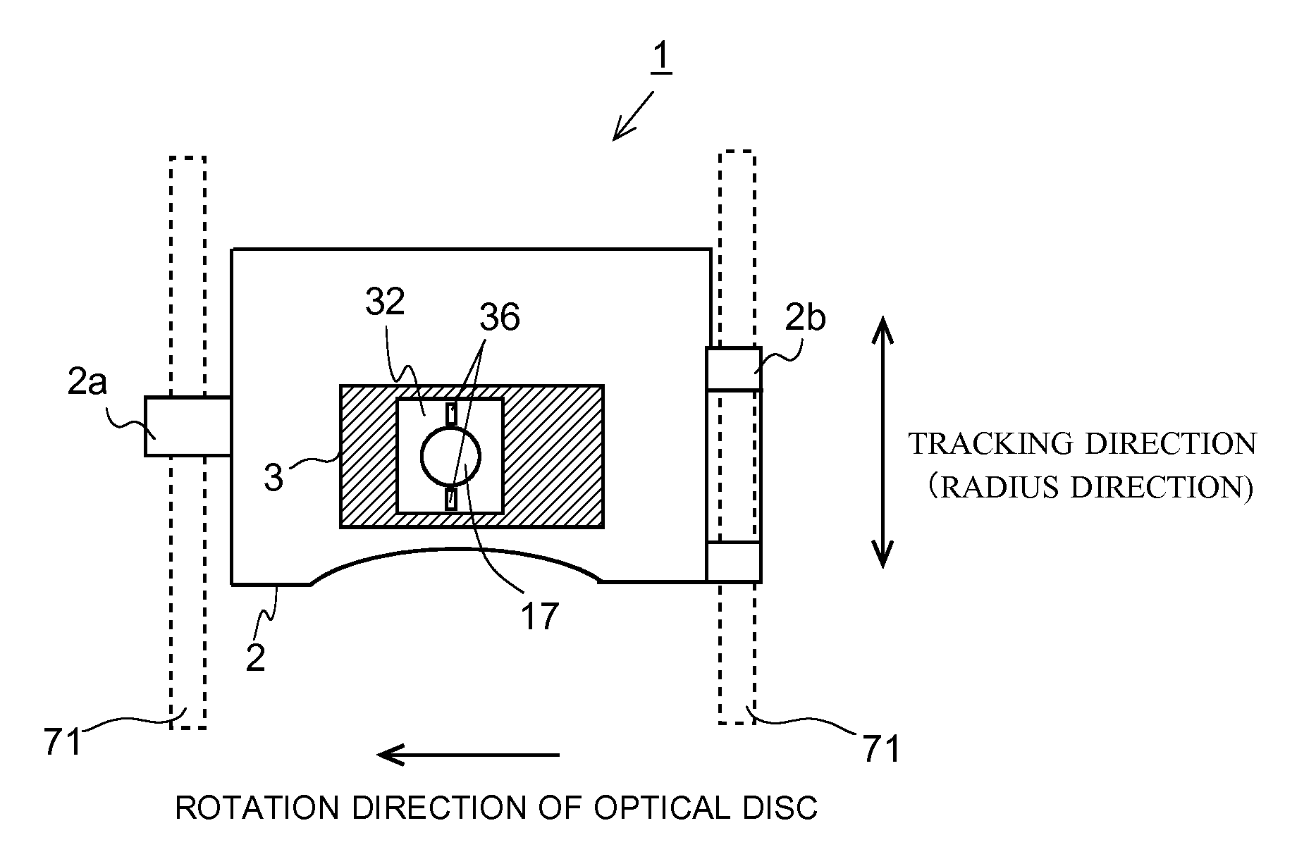
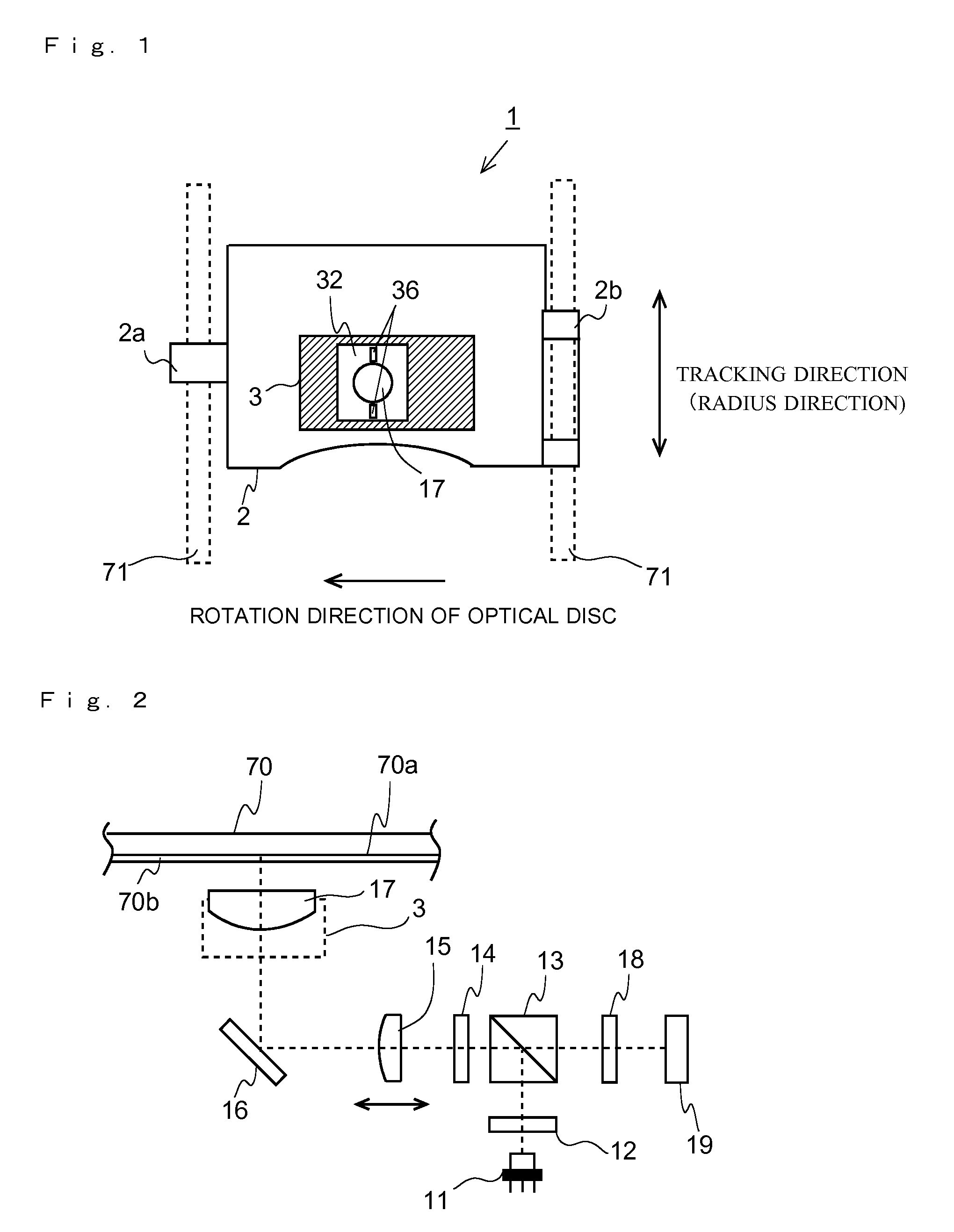
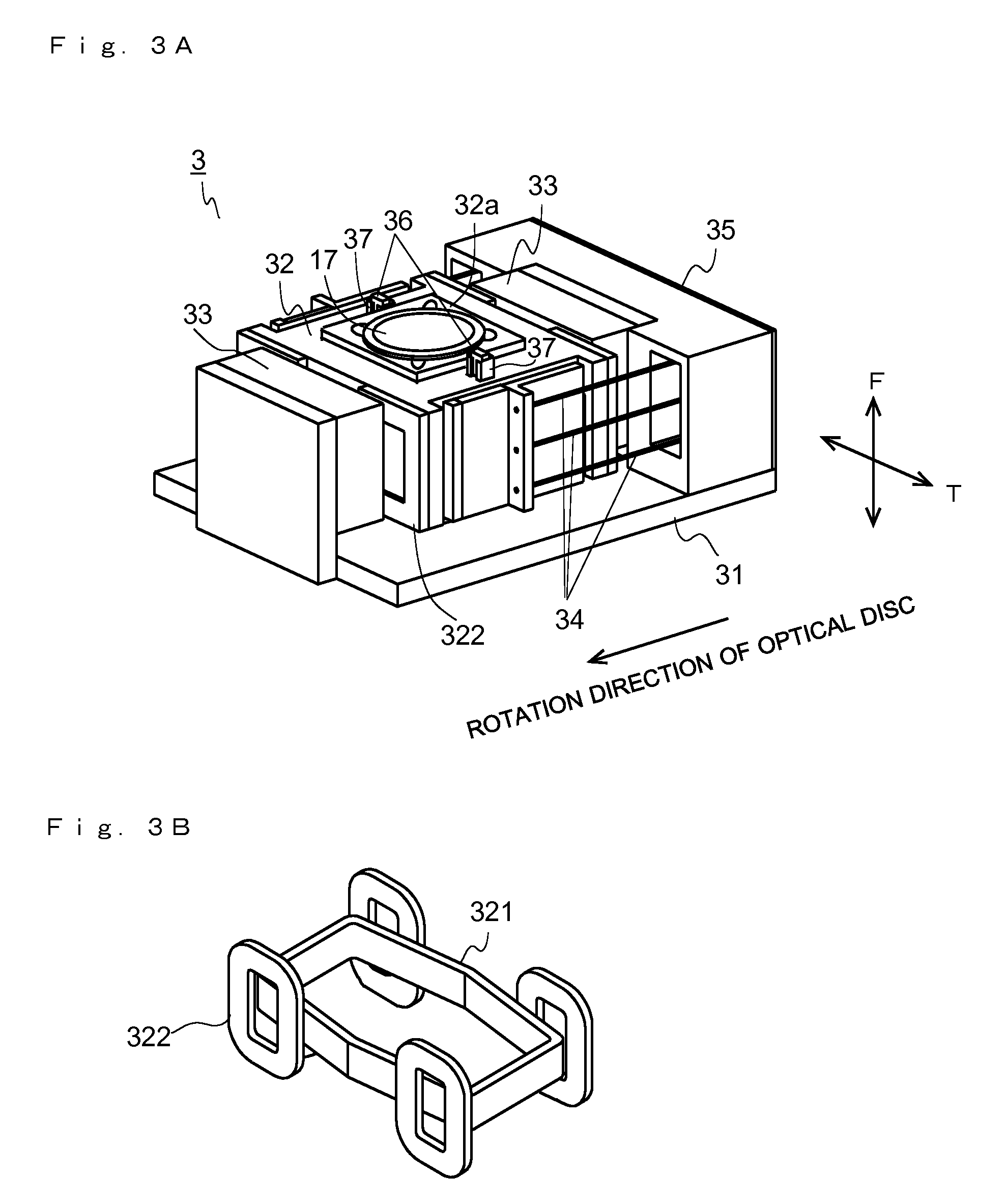
[0034]First, an outline of a structure of the optical pickup device according to this embodiment will be described with reference to FIGS. 1, 2, 3A and 3B. FIG. 1 is a plan view schematically showing a structure of the optical pickup device embodying the present invention. FIG. 2 schematically shows a structure of an optical system provided in the optical pickup device embodying the present invention. FIG. 3A is a perspective view schematically showing an entire structure of an objective lens actuator provided in the optical pickup device embodying the present invention; FIG. 3B is a perspective view schematically showing a structure of a coil provided in the objective lens actuator embodying the present invention.

[0035]As shown in FIG. 1, the optical pickup device 1 according to this embodiment is provided with a slider base 2. T...


PUM

PropertyMeasurementUnit
wavelengthaaaaaaaaaa
thicknessaaaaaaaaaa
thicknessaaaaaaaaaa

Abstract

An optical pickup device is provided with: a light source; an objective lens focusing light from the light source on an information recording surface of an optical recording medium; a lens holder holding the objective lens; and a collision prevention member provided on the lens holder, and preventing collision between the optical recording medium and the objective lens. The collision prevention member is formed with a sheet member, and is disposed on the lens holder so that a side surface, substantially parallel to a thickness direction, of the sheet member faces the information recording surface.

Description

[0001]This application is based on Japanese Patent Application No. 2008-264841 filed on Oct. 14, 2008, the contents of which are hereby incorporated by reference.BACKGROUND OF THE INVENTION[0002]1. Field of the Invention[0003]The present invention relates to an optical pickup device, and more particularly, to an optical pickup device provided with a collision prevention member preventing collision between an objective lens focusing light from a light source on an information recording surface of an optical recording medium and the optical recording medium.[0004]2. Description of Related Art[0005]Optical recording media such as a compact disc (hereinafter, referred to as CD) and a digital versatile disc (hereinafter, referred to as DVD) are widely spread. Moreover, recently, a blue-ray disc (hereinafter, referred to as BD) on which a large amount of information can be recorded has been put into practical use. When information is read from and written in the optical recording medium a...

Claims


Application Information

Patent Timeline
Patent Type & Authority Patents(United States)
IPC IPC(8): G11B7/00G11B7/135
CPCG11B7/1201G11B7/0933G11B7/0935G11B7/121
Inventor HAYASHI, SOUTAROMORI, FUMIAKI
Owner FUNAI ELECTRIC CO LTD
Why Eureka
Try Eureka