Liquid injector for injecting contrast medium at variable rate into a subject who is to be imaged by imaging diagnostic apparatus

a technology of contrast medium and injector, which is applied in the field of injector for injecting liquid into subjects, can solve the problems of adversely affecting the health of subjects, consuming too much contrast medium, and difficult for imaging diagnostic apparatus to capture a good fluoroscopic image of subjects

Active Publication Date: 2013-07-16
NEMOTO KYORINDO KK +1
View PDF15 Cites 23 Cited by
  • Summary
  • Abstract
  • Description
  • Claims
  • Application Information

AI Technical Summary

Benefits of technology

[0013]It is therefore an object of the present invention to provide a liquid injector which is capable of injecting a contrast medium into a subject in order to maintain a state in which the image contrast produced by the injected contrast medium approximates an optimum level.
[0014]A liquid injector according to the present invention has a liquid injection mechanism, a pattern storing means, and a rate controlling means. The liquid injection mechanism injects a contrast medium into a subject whose fluoroscopic image is to be captured by an imaging diagnostic apparatus. The pattern storing means registers data of a variable pattern in which an injection rate of the contrast medium varies with time. The rate controlling means varies an operating speed of said liquid injection mechanism with time according to said variable pattern. Since the injection rate of the contrast medium varies with time according to the variable pattern, a state in which the image contrast achieved by the contrast medium approximates an optimum level is maintained. Therefore, an optimum fluoroscopic image of the subject can be captured. The contrast medium is consumed in a minimum amount that is required, and hence the subject is prevented from being dosed with an unduly excessive amount of contrast medium.

Problems solved by technology

Therefore, even when a contrast medium is injected into a subject using the conventional liquid injector, it is difficult for the imaging diagnostic apparatus to capture a good fluoroscopic image of the subject.
Consequently, the contrast medium is consumed too much, and tends to adversely affect the subject's health.
Simply reducing the amount of contract medium to be injected into the subject would not solve the problem because the period of time in which the CT value approximates the optimum level would be reduced, making it more difficult to capture a good fluoroscopic image of the subject.

Method used


Image

  • Liquid injector for injecting contrast medium at variable rate into a subject who is to be imaged by imaging diagnostic apparatus
  • Liquid injector for injecting contrast medium at variable rate into a subject who is to be imaged by imaging diagnostic apparatus
  • Liquid injector for injecting contrast medium at variable rate into a subject who is to be imaged by imaging diagnostic apparatus

Examples


Embodiment Construction

Arrangement of the liquid injector:

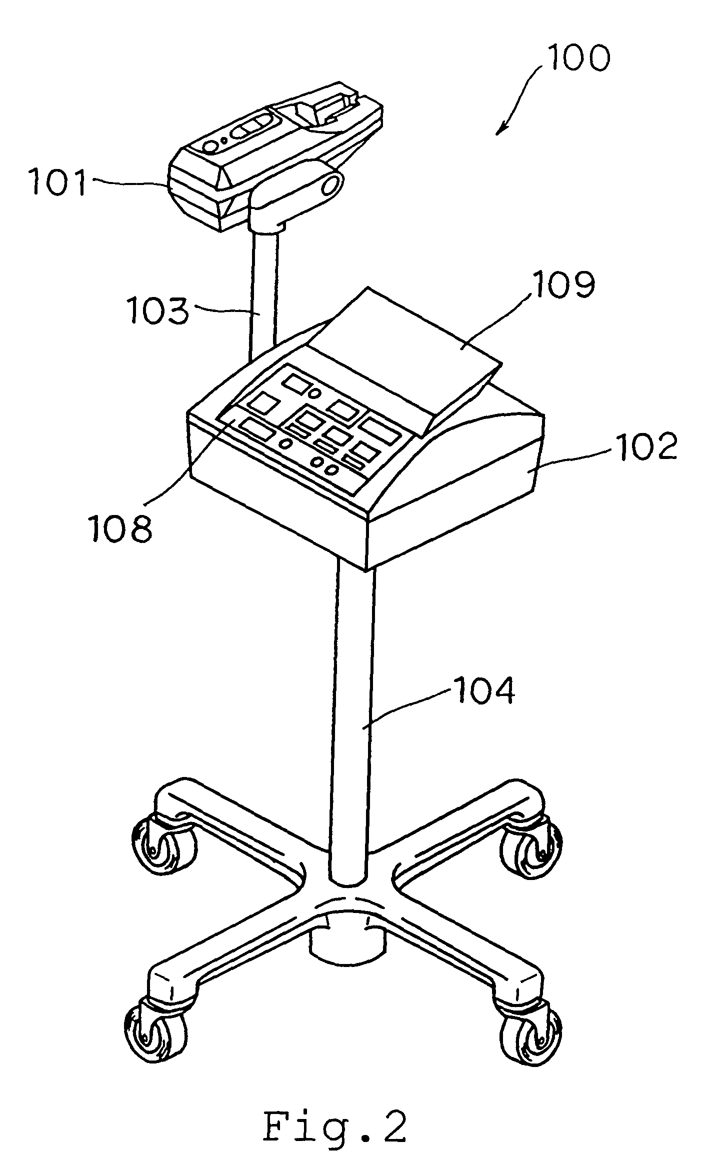
[0032]As shown in FIG. 2, liquid injector 100 according to an embodiment of the present invention comprises injection head 101 and main body 102. Main body 102 is mounted on the upper end of stand 103. Arm 104 is vertically mounted on a side wall of main body 102, and injection head 110 is mounted on the upper end of arm 104.

[0033]As shown in FIG. 3, liquid injector 100 is used near imaging unit 301 of CT scanner 300 which serves as an imaging diagnostic apparatus. Liquid injector 100 injects a contrast medium as a liquid from liquid syringe 200 into a subject (not shown) who is to be imaged by CT scanner 300.

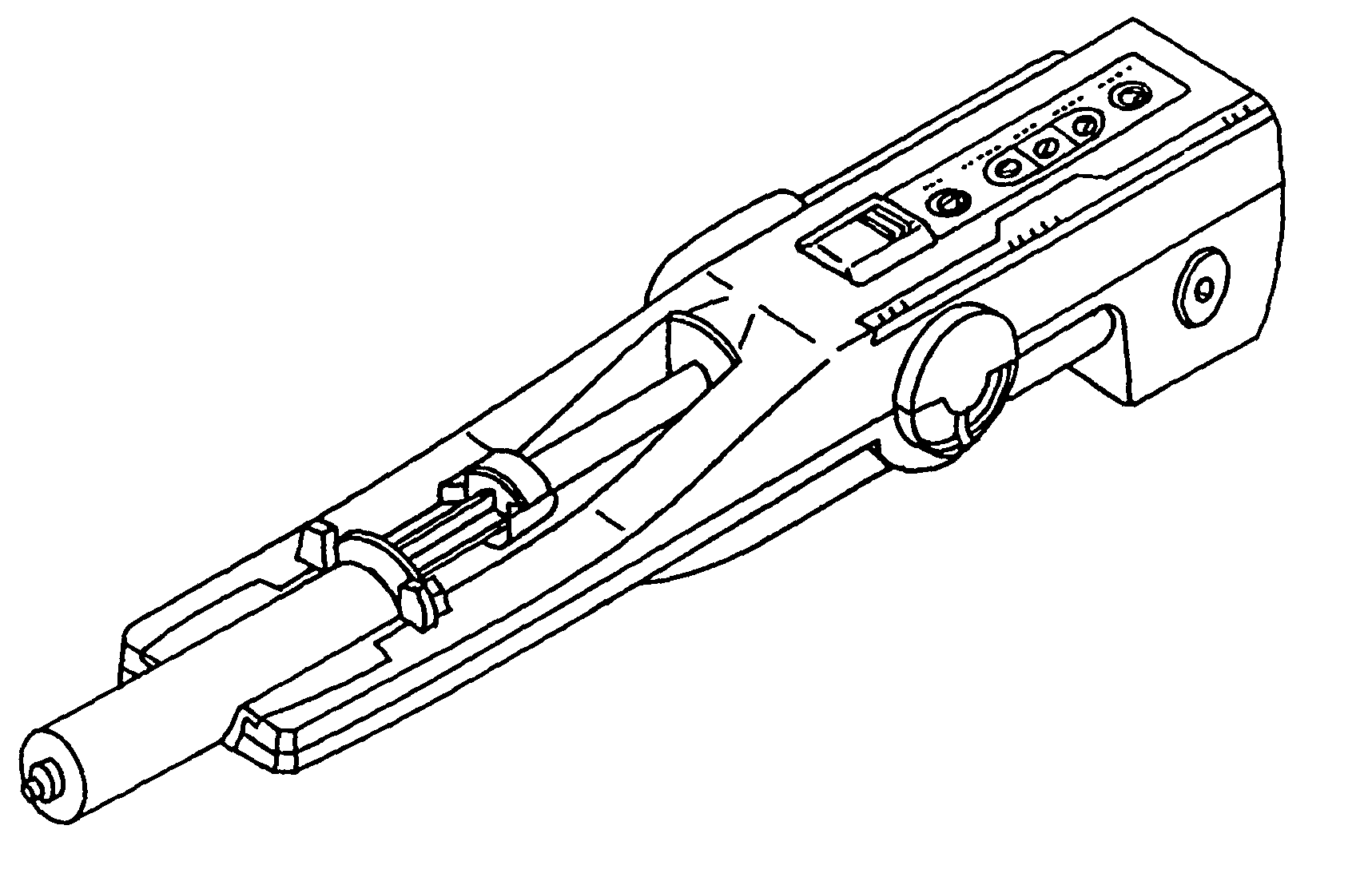
[0034]As shown in FIG. 4, liquid syringe 200 comprises cylinder 201 and piston 202 slidably inserted in cylinder 201. Injection head 101 of liquid injector 100 holds cylinder 201 of syringe 200, which is replaceable, in recess 106 that is defined in an upper surface of injection head 101. Injection head 101 has syringe actuating mechanism 107 ...


PUM


Abstract

A liquid injector registers the data of a variable pattern in which an injection rate of a contrast medium varies with time. The injection rate of the contrast medium varies with time according to the variable pattern for maintaining a state in which the image contrast achieved by the contrast medium approximates an optimum level.

Description

BACKGROUND OF THE INVENTION[0001]1. Field of the Invention[0002]The present invention relates to a liquid injector for injecting a liquid into a subject, and more particularly to a liquid injector for injecting a liquid into a subject who is to be imaged by an imaging diagnostic apparatus such as a CT (Computed Tomography) apparatus, an MRI (Magnetic Resonance Imaging) apparatus, an angiography apparatus, or the like.[0003]2. Description of the Related Art[0004]Presently available imaging diagnostic apparatus for capturing fluoroscopic images of subjects include CT scanners, MRI apparatus, PET (Positron Emission Tomography) apparatus, ultrasonic diagnostic apparatus, CT angiography apparatus, MR angiography apparatus, and ultrasonograph.[0005]When such an imaging diagnostic apparatus is used to capture a fluoroscopic image of a subject, it is occasionally practiced to inject a liquid such as a contrast medium or a saline solution into the subject. There have been liquid injectors in...

Claims


Application Information

Patent Timeline
Patent Type & Authority Patents(United States)
IPC IPC(8): A61M37/00G01R33/28A61B5/055A61M5/00A61M5/145A61M5/172A61M31/00
CPCA61M5/1456A61M5/172A61M31/005A61M5/007G05D7/0617A61M2205/52A61M2005/14208
Inventor MASUDA, KAZUMASAHATCHO, ATSUSHI
Owner NEMOTO KYORINDO KK
Why Eureka
Try Eureka