System and method for determining system charging current

a charging current and system technology, applied in the field of three-phase electrical power systems, can solve problems such as arcs, unpredictable electrical arc hazards and associated effects on electrical equipment, and insulation between phase-to-phas

Active Publication Date: 2013-07-16
PAUL DEV
View PDF8 Cites 17 Cited by
  • Summary
  • Abstract
  • Description
  • Claims
  • Application Information

AI Technical Summary

Benefits of technology

[0008]The present disclosure describes an apparatus and method for determining system charging current in a three-phase power system. This method provides the best assurance of avoiding dangerous transient over-voltages in a medium voltage power system, because the system is kept grounded through a suitable neutral resistor. All neutral resistor values will provide ratio (IF/IR) equal to or less than 1.414 but greater than 1.275 will be suitable resistors for HR grounded power system. The apparatus may include a capacitance discharging disconnect switch, a fused interrupter switch with a current limiting fuse, capable of remote operation, a fixed resistor with a parallel contactor contact, capable of remote closure, sensitive clamp on type current transformers capable of providing input to a system charging current recorder. A direct recorder is capable of operating with two current inputs, IR and IF. It is a smart package capable of making engineering calculations based on a simple equation, providing IF/IR ratio for suitable neutral resistor tap as well being capable of calculating the average of several calculated values of the system charging current which may be stored in memory (data storage unit) during measurements. A micro-processor ground fault protection relay is provided for monitoring the neutral resistor current accurately. In addition, this relay does not need to provide tripping of the secondary breaker but provides an alarm at a set current pickup. A similar relay may be used in a phase-to-ground circuit. Then, a recording can be made of the fault current through the phase conductor when grounded without any resistance in the circuit. This current IF is the vector sum of IR (current through the neutral resistor which is EL-N/RN) and total system charging current Ic. Finally the expression Ic=√(IF2−IR2) is used to determine the inherent system charging current. The method of determining system charging curren...

Problems solved by technology

Electrical arc hazards and associated affects on electrical equipment are unpredictable.
Arcs may occur when equipment insulation between phase-to-phase or phase-to-ground fails.
The intensity of arc damage is related to fault current magnitude at insulation failure.
However, this method may not provide accurate data as the sneak capacitance to ground of power system components due to their installation configuration cannot be determined.
This method requires several recordings of both voltage and current to determine the constant relationship between voltage and current, which may pose danger to low voltage equipment due to the presence of medium voltage as the system is fully energized.
This method poses a danger both to equipment and to personnel during measurements, and it is uncertain how the power system voltage regulation and dynamic nature of the energized power system at the time of making measurements would affect the foreign low voltage when power system voltage is present.
However, it is p...

Method used


Image

  • System and method for determining system charging current
  • System and method for determining system charging current
  • System and method for determining system charging current

Examples


Embodiment Construction

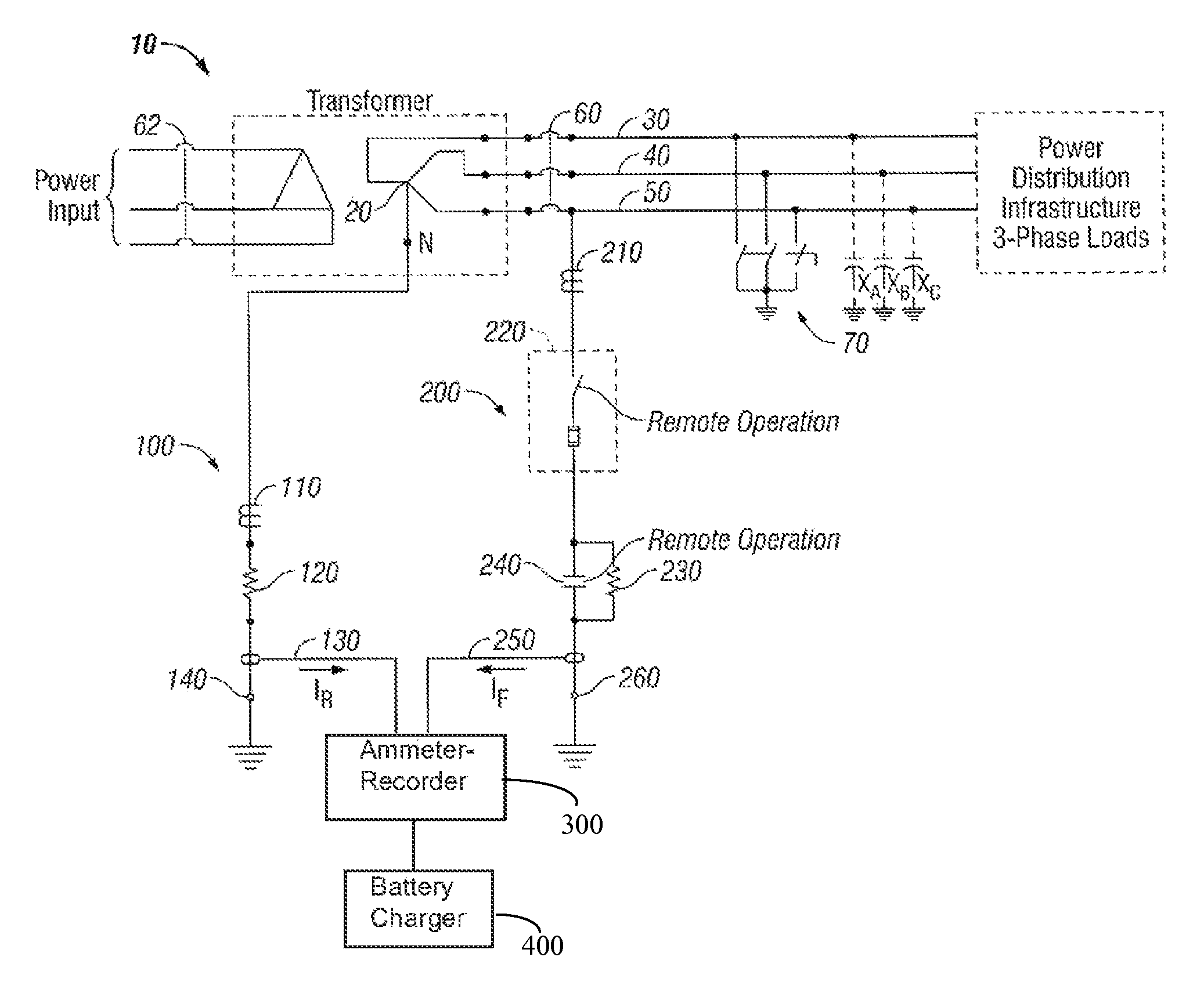
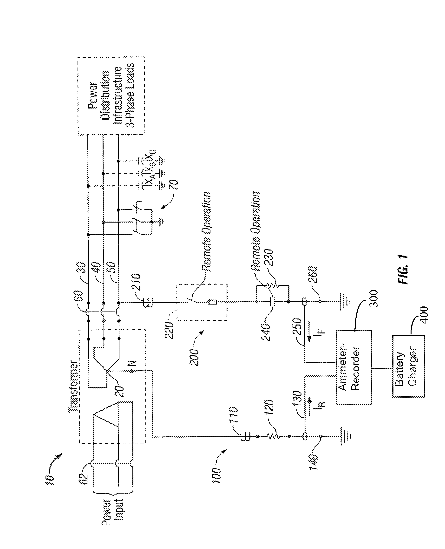
[0013]System charging current of the three-phase power system circuit 10 described and illustrated in FIG. 1 may be determined and recorded using the present method described below. The three-phase power feeder circuit 10 may have a first grounding circuit 100 interconnected with its neutral 20. The first grounding circuit 100 may have, in electrical series interconnection: a first remotely operated relay 110, a first resistor 120, a first interconnection 130 with an ammeter-recorder 300, and a first grounding electrode 140. A second grounding circuit 200 may be interconnected with any one of the three phases 30, 40, or 50 of the feeder circuit 10, and may have, in electrical series interconnection: a second remotely operated relay 210, an interrupter switch 220 which may be fused as shown, a second resistor 230 shunted across a contactor 240, a second interconnection 250 with the ammeter-recorder 300, and a second grounding electrode 260. As shown in FIG. 1, feeder circuit 10 may h...


PUM


Abstract

A system for determining a system charging current in a three-phase power system has a first grounding circuit that joins a neutral of the power transformer with a ground through a first resistor. System charged capacitance voltage in one phase is discharged through a second resistor in a second grounding circuit joining the one phase of the power system with the ground. A magnitude of the currents in the first and second grounding circuits are measured when the one phase is short circuited to ground. The preliminary system charging current is calculated as the root of the difference between the squares of the measured currents grounding circuits. The same procedure may be repeated for different values of the first resistor and for each of the phases, and the calculated preliminary system charging currents may be averaged to arrive at a net system charging current.

Description

CROSS-REFERENCE TO RELATED APPLICATIONS[0001]This application for utility patent claims the benefit of provisional patent application Ser. No. 61 / 421,042, filed on Dec. 8, 2010.STATEMENT REGARDING FEDERALLY SPONSORED RESEARCH OR DEVELOPMENT[0002]Not ApplicableBACKGROUND OF THE DISCLOSURE[0003]This disclosure relates to the field of three-phase electrical power systems and more particularly to an apparatus and method for determining the inherent system charging current of the system. Electrical arc hazards and associated affects on electrical equipment are unpredictable. Arcs may occur when equipment insulation between phase-to-phase or phase-to-ground fails. The intensity of arc damage is related to fault current magnitude at insulation failure. Power system faults data indicate that close to 75% of all faults involve ground. From this data it is clear that making the ground fault current low by using a resistance grounded power system can minimize the problem of arc hazard. The inh...

Claims


Application Information

Patent Timeline
IPC IPC(8): G01R31/08H02H9/08
CPCG01R19/2513
Inventor PAUL, DEV
Owner PAUL DEV
Why Eureka
Try Eureka