Temperature-stable CMOS voltage reference circuits

a voltage reference circuit and temperature-stable technology, applied in the field of electromechanical circuits, can solve the problems of inability to fabricate, cost reduction, and said disadvantage is a very significant factor, and achieve the effect of low quiescent current and few circuit branches

Inactive Publication Date: 2013-07-16
APTUS POWER SEMICON
View PDF18 Cites 1 Cited by
  • Summary
  • Abstract
  • Description
  • Claims
  • Application Information

AI Technical Summary

Benefits of technology

[0013]Another advantage of this invention is that IC circuits for generating a voltage reference having an area-efficient design with relatively few circuit branches and operating with relatively low quiescent current are provided.

Problems solved by technology

A disadvantage of conventional bandgap voltage reference circuits is that they comprise resistors of comparatively large value, which resistors should be matched in value with each other.
Particularly in integrated circuit (“IC”) processes, in which it is difficult or not possible to fabricate resistors which are accurate and have comparatively high resistance values, said disadvantage is a very significant factor.
The challenge in using CMOS circuit design for generating voltage references is minimizing area for cost reduction.
The problem then is to derive a circuit using standard CMOS transistors, N-channel and P-channel type transistors, for monitoring supply voltage with respect to a fixed reference.

Method used


Image

  • Temperature-stable CMOS voltage reference circuits
  • Temperature-stable CMOS voltage reference circuits
  • Temperature-stable CMOS voltage reference circuits

Examples


Embodiment Construction

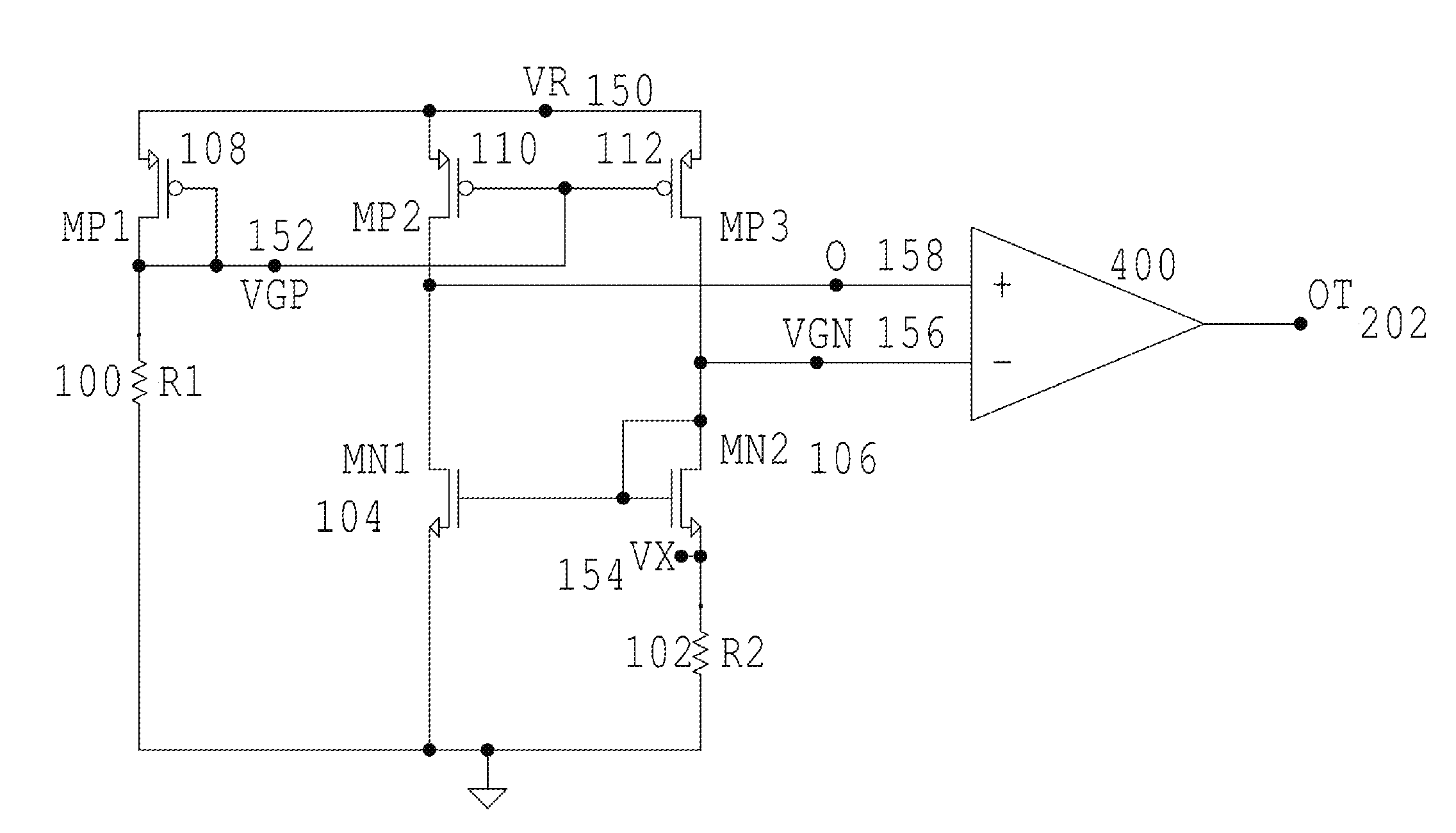
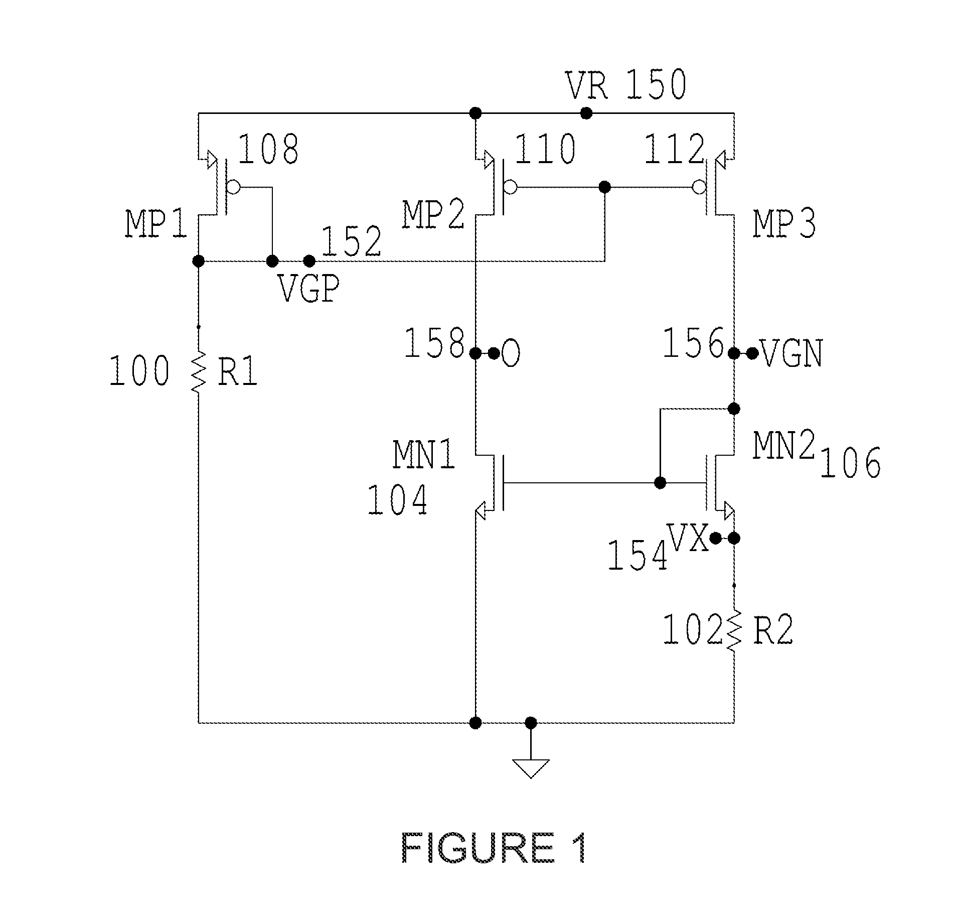
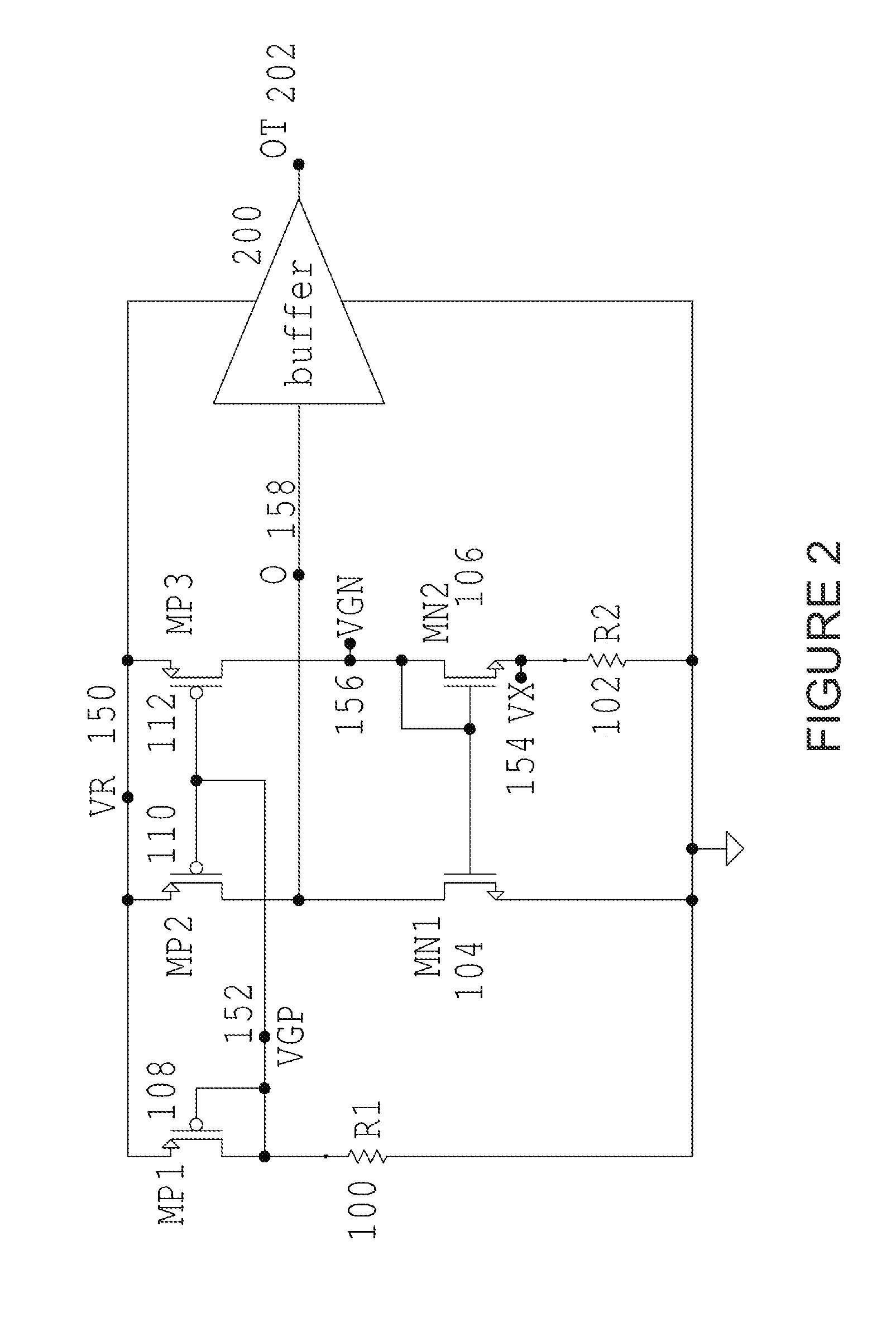
[0032]The following circuit diagrams of the present invention, illustrated in the figures, can be understood by a person having ordinary skill in the art, e.g., an electrical engineer who designs integrated circuits using common-practiced techniques including hierarchical circuit design with schematic-entry tools. Integrated circuit techniques for properly biasing circuit junctions and methods for properly biasing CMOS body junctions, and permutations thereof, are also understood by a person having ordinary skill in the art. Thus, such commonly known techniques are incorporated. Furthermore, for purposes of clarity and brevity, like elements and components may bear the same designations and numbering throughout the figures. Moreover, N-type MOSFET (metal-oxide-semiconductor field-effect transistor) can be referred to as NMOS and P-type MOSFET (metal-oxide-semiconductor field-effect transistor) can be referred to as PMOS.

[0033]FIG. 1 illustrates a comparator mode CMOS circuit design ...


PUM


Abstract

A temperature stable comparator circuit, comprised of: a branch C having a first end, a second end, a first type-1 device and first type-2 device, wherein the first type-1 device and the first type-2 device are connected to a node O; a branch B having a first end, a second end, a second type-1 device, a second type-2 device, and a resistor; and a branch A having a first end, a second end, a third type-2 device and a current-control device; wherein the first ends of the branch A, branch B, and branch C are commonly connected, and the second ends of the branch B and branch C are commonly connected.

Description

CROSS REFERENCE[0001]This application claims priority from a provisional patent application entitled “A CMOS Temperature-Stable Voltage Reference” filed on Oct. 19, 2010 and having an Application No. 61 / 394,665. Said application is incorporated herein by reference.FIELD OF INVENTION[0002]The present invention relates to electronic circuits and, in particular, to CMOS (complementary metal oxide semiconductor) circuits for generating temperature stable voltage references and to CMOS circuits for generating temperature stable voltage comparators.BACKGROUND[0003]Voltage references are required to provide a substantially constant output voltage irrespective of changes in input voltage, output current, or temperature. Such references are used in many design applications, such as stable current references, multipliers, control circuits, portable meters, two-terminal references and process controllers, a comparator mode for causing a logic transition, and a servo mode for generating a fixed...

Claims


Application Information

Patent Timeline
Patent Type & Authority Patents(United States)
IPC IPC(8): H03K5/153
CPCG05F3/242
Inventor FLOYD, BRIAN HAROLD
Owner APTUS POWER SEMICON
Why Eureka
Try Eureka