Image signal converting apparatus and image display apparatus
a technology of image signal and converting apparatus, which is applied in the direction of electrical apparatus, color television details, instruments, etc., can solve the problems of achieve the effect of improving image luminance and deterioration of image color reproducibility
- Summary
- Abstract
- Description
- Claims
- Application Information
AI Technical Summary
Benefits of technology
Problems solved by technology
Method used
Image
Examples
first embodiment
[First Embodiment]
(Schematic Description of Projection Image Display Apparatus)
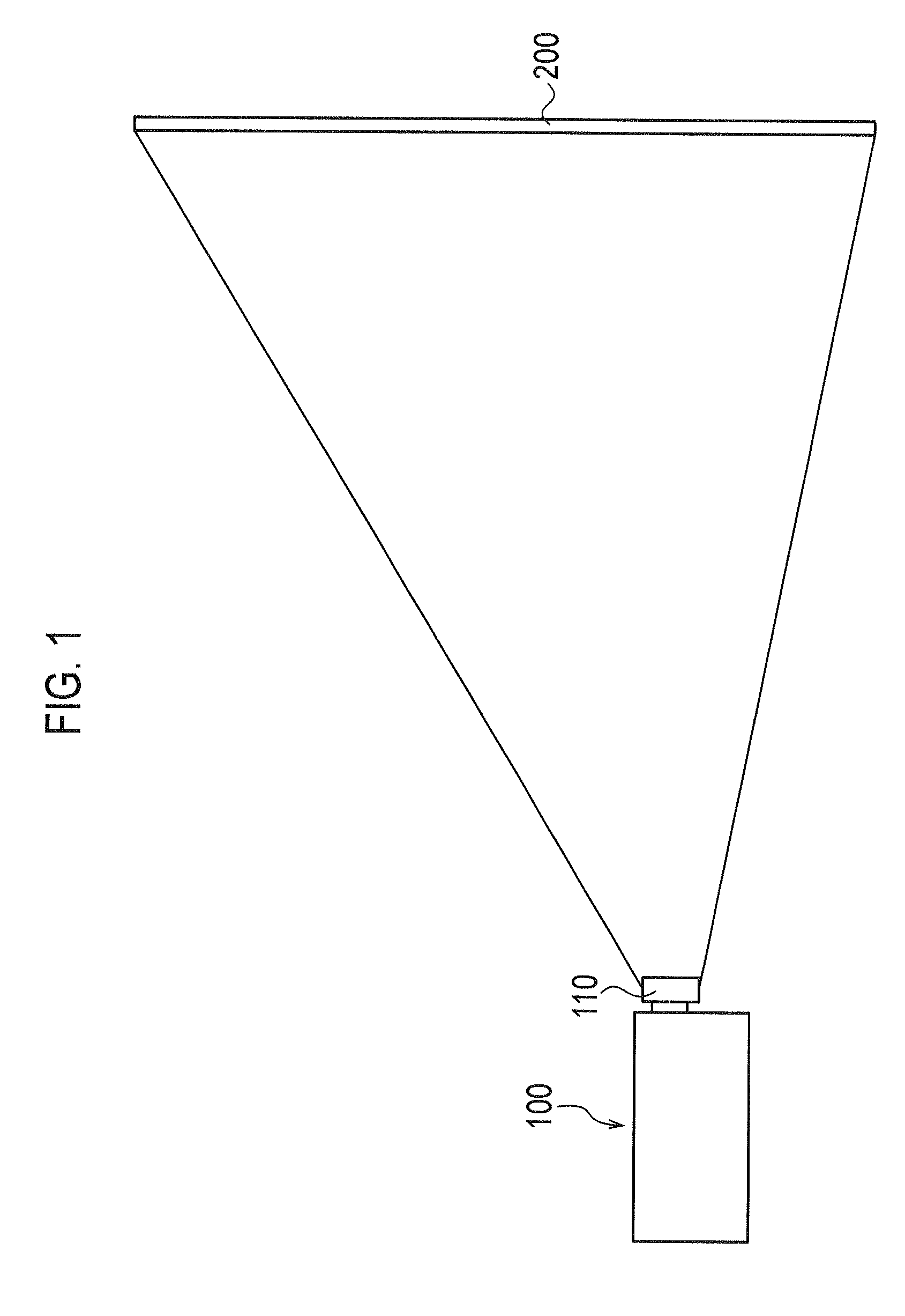
[0036]A summary of a projection image display apparatus of the first embodiment is described below with reference to drawings. FIG. 1 is a schematic diagram of the projection image display device 100 of the first embodiment of the invention.
[0037]As shown in FIG. 1, the projection image display apparatus 100 includes a projection lens unit 110, and projects image light magnified by the projection lens unit 110 on a screen 200. As described later, the projection image display apparatus 100 uses yellow component light as fourth color component light in addition to red component light, green component light and blue component light.
(Schematic Configuration of Lighting Unit)
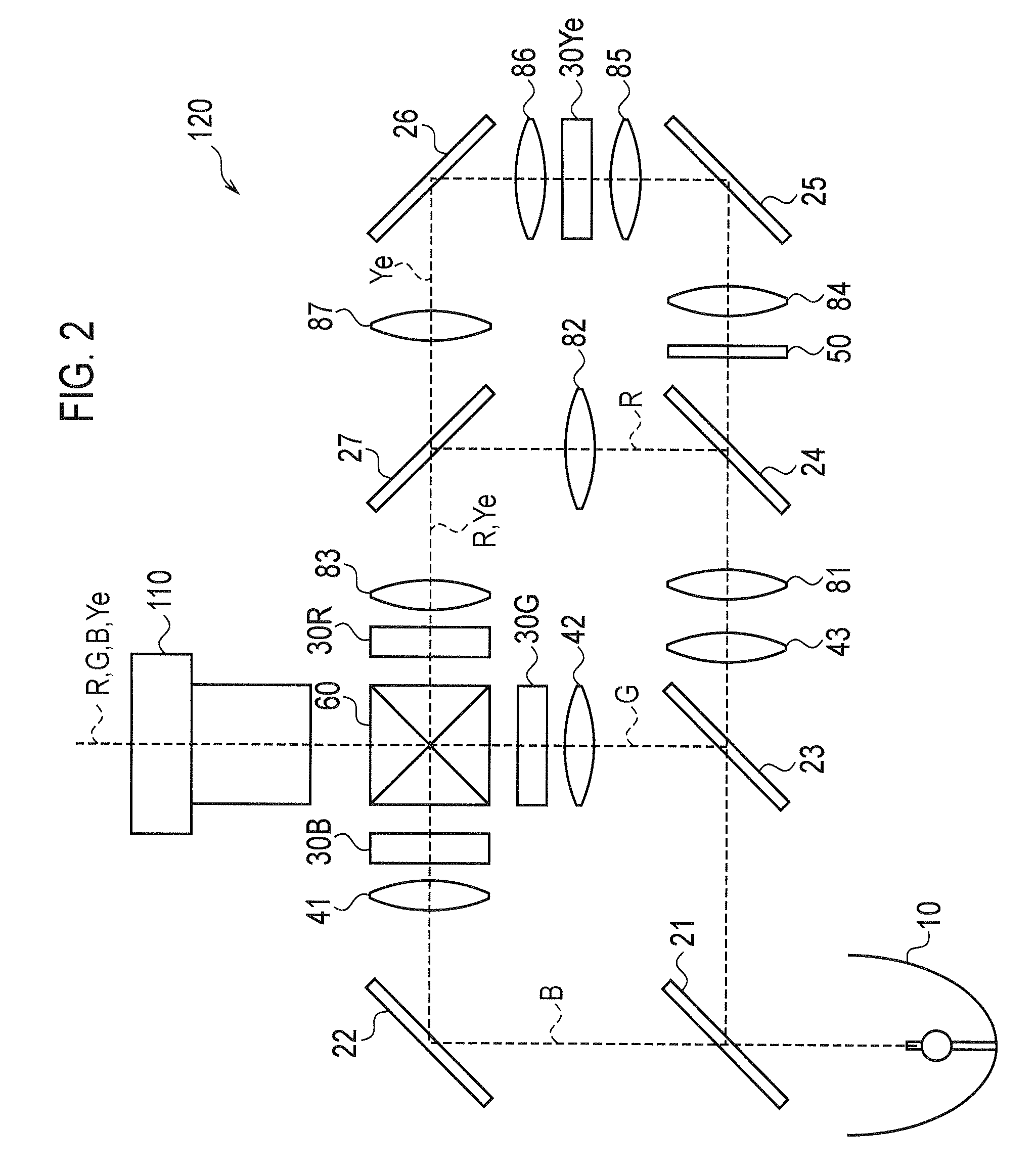
[0038]A schematic configuration of a lighting unit of the first embodiment is described below with reference to the drawings. FIG. 2 is a view showing a schematic configuration of the lighting unit 120 of the first embodiment. It should be...
second embodiment
[Second Embodiment]
[0108]A second embodiment is described below with reference to drawings. Differences between the first embodiment described below and the second embodiment are mainly described below.
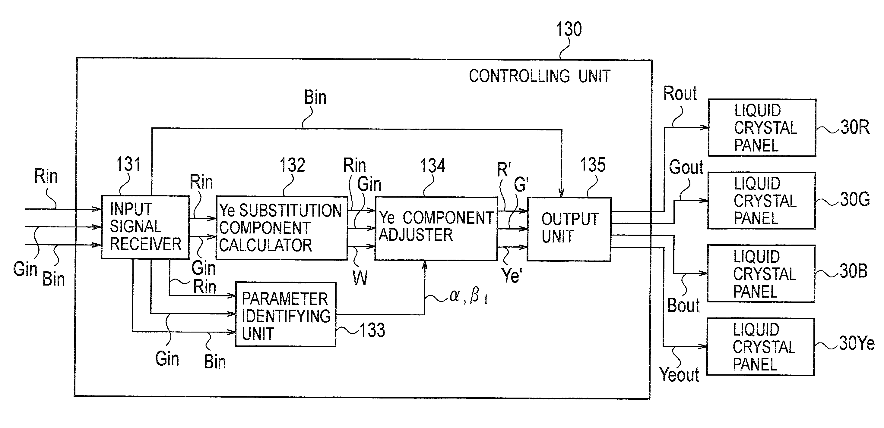
[0109]Specifically, in the above described first embodiment, the projection image display apparatus 100 outputs the blue input signal Bin directly to the liquid crystal panel 30B as the blue output signal Bout. In contrast, in the second embodiment, the visibilities of red component light, green component light, blue component light, and yellow component light are taken into consideration, and the projection image display apparatus 100 adjusts the red output signal Rout, a green output signal Gout, a blue output signal Bout, and a yellow output signal Yeout.
(Functions of the Projection Image Display Apparatus)
[0110]Functions of the projection image display device 100 of the second embodiment are described below by referring to drawings. FIG. 7 is a block diagram showing the functions ...
third embodiment
[Third Embodiment]
[0161]A third embodiment is described below with reference to drawings. Differences between the first embodiment and the third embodiment are mainly described below.
[0162]More specifically, in the above-described first embodiment, a superimposition amount of the yellow component light (Ye substitution signal W) is determined from an input signal having a lower intensity between the red input signal Rin and the green input signal Gin.
[0163]In contrast, in the third embodiment, a superimposition amount of yellow component light (Ye substitution signal W) is determined from a mean value of luminance of respective pixels included in a target region and a mean value of saturation thereof.
(Function of the Projection Image Display Apparatus)
[0164]A function of a projection image display apparatus 100 of the third embodiment is described below with reference to the drawings. FIG. 15 is a view for explaining the functions of the projection image display apparatus 100 (contr...
PUM
 Abstract
Description
Claims
Application Information
 - R&D
- Intellectual Property
- Life Sciences
- Materials
- Tech Scout
- Unparalleled Data Quality
- Higher Quality Content
- 60% Fewer Hallucinations
Browse by: Latest US Patents, China's latest patents, Technical Efficacy Thesaurus, Application Domain, Technology Topic, Popular Technical Reports.
© 2025 PatSnap. All rights reserved.Legal|Privacy policy|Modern Slavery Act Transparency Statement|Sitemap|About US| Contact US: help@patsnap.com


