Concrete sandwich wall insert

a technology of concrete and sandwich walls, applied in the direction of walls, auxiliary members of forms/shuttering/falseworks, building repairs, etc., can solve the problems of foam movement or damage, small structural rigidity of insulation foam, easy warping or breaking of concrete, etc., to achieve the effect of reducing labor and downtime, enhancing the strength of bar assemblies, and increasing the economic utilization of forming panels

Inactive Publication Date: 2013-07-23
PRECISE FORMS
View PDF10 Cites 7 Cited by
  • Summary
  • Abstract
  • Description
  • Claims
  • Application Information

AI Technical Summary

Benefits of technology

[0009]The present invention overcomes the problems outlined above, and provides greatly improved insert assemblies operable to be located between a pair of opposed concrete forming panels prior to a concrete pour to yield a concrete sandwich wall structure. Broadly speaking, such inserts include a sheet of thermal insulating material presenting a pair of opposed side surfaces, with a reinforcing bar assembly located adjacent each of the opposed sheet faces.
[0010]Connection structure operably secures the reinforcing bar assemblies to the sheet so as to inhibit significant relative movement between the sheet and reinforcing bar assemblies during a concrete pour.
[0012]The reinforcing bar assemblies are preferably in the form of a regular grid made up of interconnected, generally horizontal and generally vertical reinforcing bars. Advantageously, the bars are welded together to enhance the strength of the bar assemblies.
[0013]The insert assemblies of the invention are normally prefabricated and are erected on-site with conventional concrete form panels. However, owing to the construction of the insert assemblies, they can readily be field-modified by attachment of electrical boxes and conduit. This assures that the boxes are precisely placed where desired. Once a completed sandwich wall structure form is erected with inserts between spaced form panels, concrete is poured into the form. Given the fact that the insert assemblies are substantially rigidified, concrete can be separately poured on opposed sides of the insulating sheets of the insert assemblies, without fear of warpage or breaking of the sheets.
[0014]The insert assemblies of the invention permit rapid construction of concrete sandwich walls with a minimum of labor and downtime. This in turn permits more economic utilization of the forming panels and ancillary forming equipment than has heretofore been possible.

Problems solved by technology

However, there are a number of problems associated with the construction of concrete sandwich walls.
The insulating foam has very little structural rigidity, and can easily become warped or broken by the concrete as it is poured.
Moreover, while the reinforcing bars are placed precisely relative to the foam material prior to the pour, the bars tend to float or shift during the pour, often leading to foam movement or damage.
But if the bars shift during the pour, the spokes can penetrate the foam, degrading the entire sandwich wall.
This is a time-consuming, labor-intensive undertaking normally extending over several days, which necessarily ties up the form panels and ancillary forming equipment resulting in lost opportunities to do other construction jobs.

Method used


Image

  • Concrete sandwich wall insert
  • Concrete sandwich wall insert
  • Concrete sandwich wall insert

Examples


Embodiment Construction

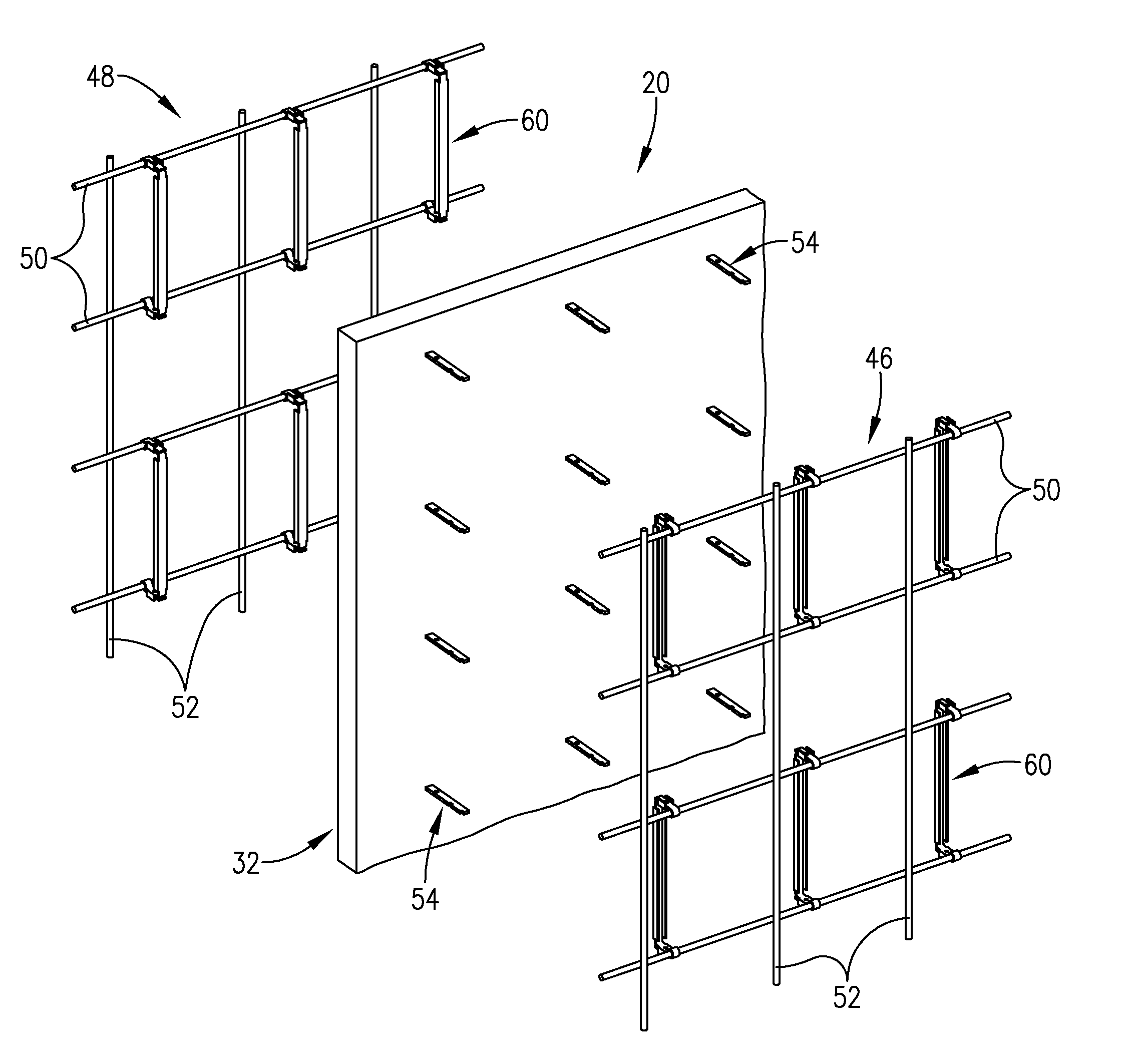
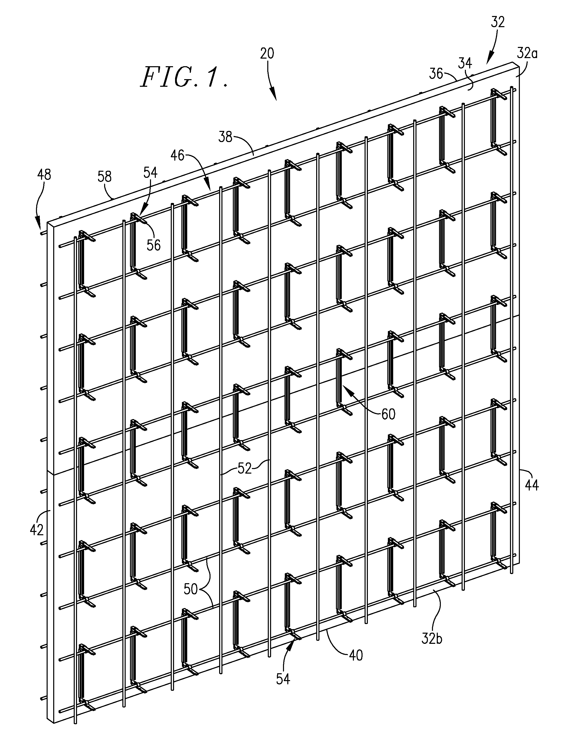
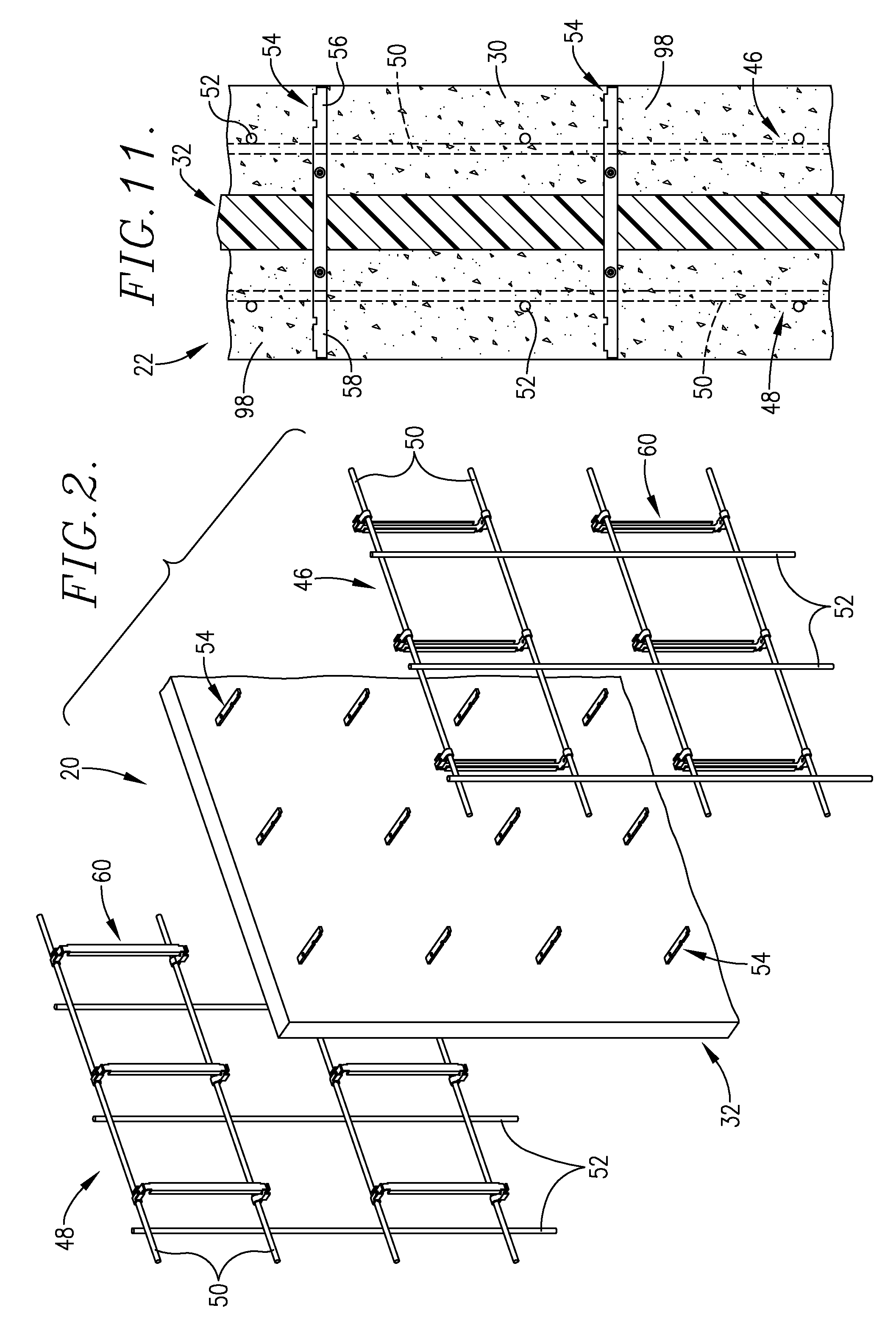
[0026]The present invention is directed in part to thermally insulating insert assemblies 20 of a type used during construction of complete, poured concrete sandwich wall structures 22 (FIG. 11). That is to say, the inserts 20 of the invention are designed to be placed within an upright space 24 between a pair of opposed, upright concrete form panels 26 and 28. Thereupon, concrete 30 is poured into the space 24 in surrounding relationship to insert assembly 20, and allowed to cure, thereby providing the complete poured sandwich wall structure 22.

[0027]In more detail, the preferred assembly 20 includes an upright body or sheet 32 of thermally insulative material, such as a synthetic resin foam, presenting a pair of opposed side surfaces 34, 36, top and bottom surfaces 38, 40, and end surfaces 42, 44. As such, the sheet 32 is of square (e.g., 8′ by 8′) or rectangular configuration, as may be desired. In the embodiment illustrated in FIG. 1, the sheet 32 is made up of a pair of aligned...


PUM


Abstract

Improved concrete form insert assemblies (20) are provided for use in the construction of thermally insulated poured concrete sandwich wall structures (22). The insert assemblies (20) include a central sheet (32) of insulative material such as synthetic resin foam, which is preferably encapsulated by a sheath (78) to enhance the structural integrity of the sheet (32). A pair of reinforcing bar assemblies (46, 48) preferably made up of welded-together horizontal and vertical bars (50, 52) are respectively positioned adjacent the side surfaces (34, 36) of the sheet (32). The bar assemblies (46, 48) are secured to sheet (32) by means of connector elements (54) extending through the sheet (32) and presenting oppositely outwardly extending, apertured segments (56, 58). Connector bars (60) extend between adjacent horizontal bars (50) and include an elongated channel section (62) abutting the sheet (32) and a pair of endmost ears (64) which are secured to the bars (50) to thereby support the bar assemblies (46, 48) in standoff relationship to the sheet (32). The insert assemblies (20) are preferably prefabricated and installed at a construction site between upright concrete form panels (26, 28), as straight wall and corner units (80). The assemblies (20) may also be field-modified by installation of electrical wiring including boxes (94) and conduit (96). Concrete (30) is then poured, resulting in a complete sandwich wall structure (22). Use of the assemblies (20) significantly reduces construction time and costs, and thereby permits more economical usage of the form panels (26, 38).

Description

BACKGROUND OF THE INVENTION[0001]1. Field of the Invention[0002]The present invention is broadly concerned with improved apparatus and methods for the fabrication of poured concrete sandwich walls having a central, thermally insulating sheet or section. More particularly, the invention is concerned with insert assemblies which are preferably prefabricated and field-modified as needed, and are then positioned between conventional concrete form panels. The insert assemblies include a central insulative sheet with a pair of reinforcing bar assemblies adjacent each face of the sheet and operably coupled to the latter by means of cross-connectors.[0003]2. Description of the Prior Art[0004]Poured concrete wall structures may be equipped with one or more internal, upright sheets or bodies of thermal insulation, typically made up of a synthetic resin foam material. Such wall structures are known in the art as sandwich walls, referring to the fact that the insulating foam is sandwiched betwe...

Claims


Application Information

Patent Timeline
Patent Type & Authority Patents(United States)
IPC IPC(8): E04B1/16
CPCE04B1/16E04C2/044E04G17/06E04G11/18H02G3/121E04C2002/047
Inventor TRIMMER, DOUGLASDUGGER, DAN
Owner PRECISE FORMS
Why Eureka
Try Eureka