Electromagnetic actuating unit

a technology of electric actuation and actuator, which is applied in the field of hydraulic directional valve, can solve the problem that the requirements are only insufficiently taken into account in the known hydraulic directional valve, and achieve the effect of low pressure loss and high control stability

Active Publication Date: 2013-07-23
SCHAEFFLER TECH AG & CO KG
View PDF12 Cites 6 Cited by
  • Summary
  • Abstract
  • Description
  • Claims
  • Application Information

AI Technical Summary

Benefits of technology

[0008]The underlying object of the invention is therefore to create a hydraulic directional valve which has, especially in low temperature, low pressure losses and that has, even at high temperatures, a high control stability.
[0013]Therefore, the expansion of the control section can be dimensioned such that the overlapping of the working port by the control section is minor, when the working port is blocked in the direction of a pressure medium conveying structure communicating with an supply port. Therefore, a relatively large flow cross section is present between the working port and the discharge port, by way of which pressure losses within the directional valve are minimized. With rising temperature, the axial extension of the control section is increasing, by way of which the volume flow from the working port to the discharge port is throttled and, therefore, a high control stability of the connected load, for instance a camshaft adjuster, is achieved.
[0014]Advantageously, the control section has, in the direction perpendicular to the displacement direction of the control piston, the same or at least approximately the same coefficient of linear thermal expansion as the base body. In this manner, jamming of the control piston inside the valve housing at high temperatures is avoided, or that leakage reaches intolerable high values in low temperatures.

Problems solved by technology

These requirements are only insufficiently taken into account in the known hydraulic directional valve.

Method used


Image

  • Electromagnetic actuating unit
  • Electromagnetic actuating unit

Examples


Embodiment Construction

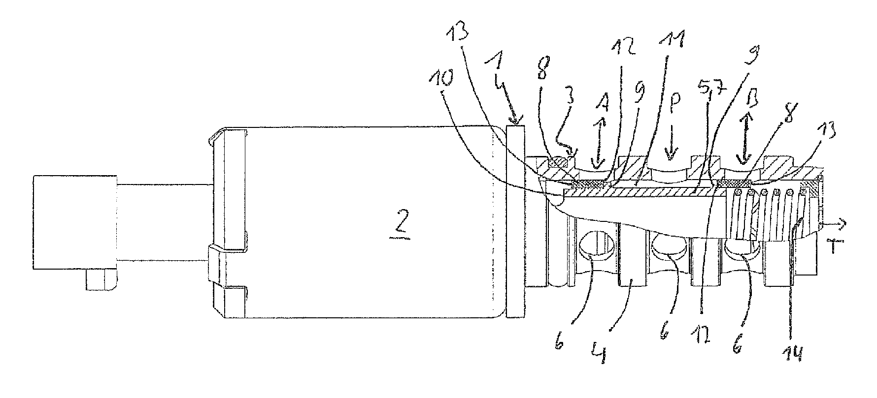
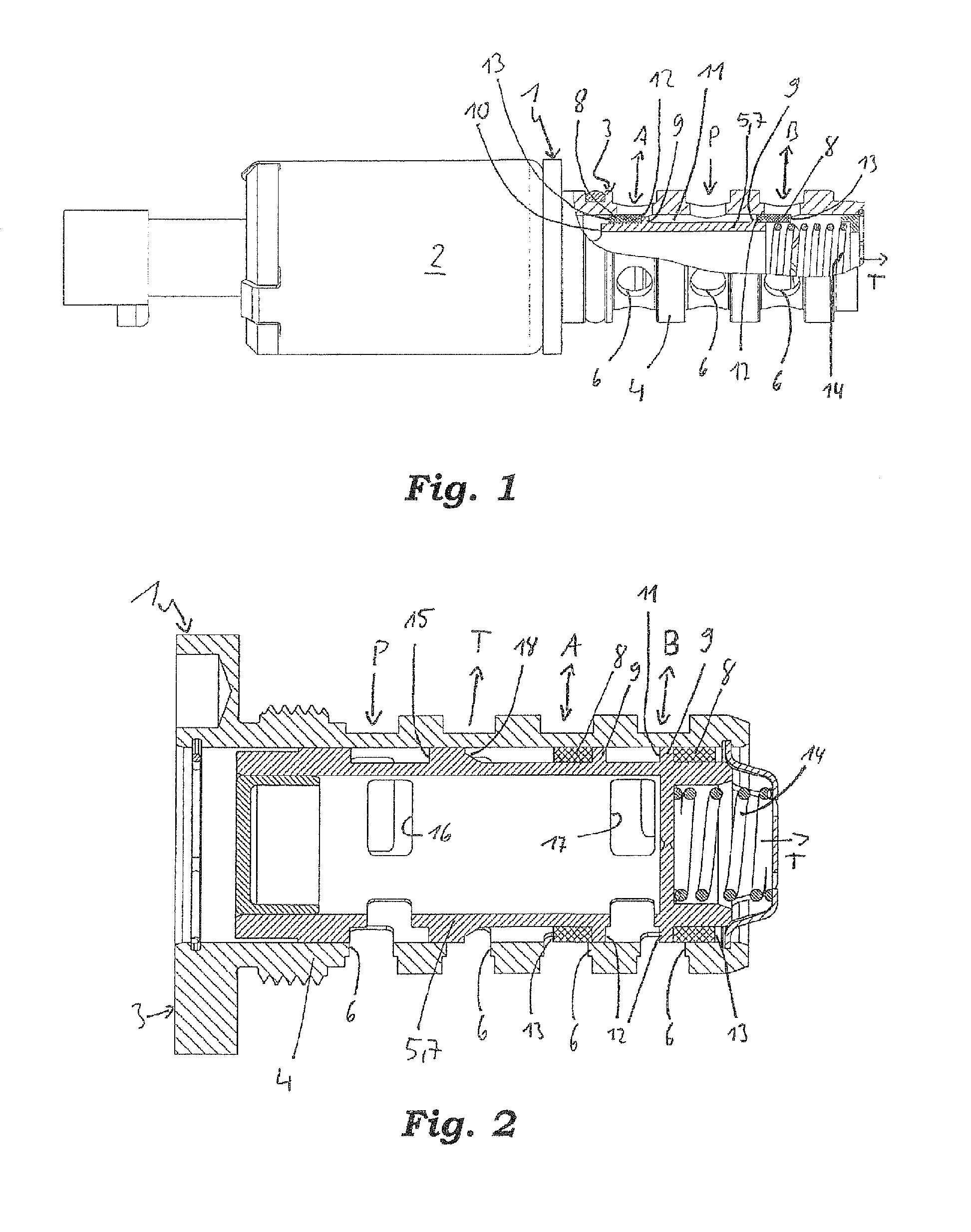
[0020]FIGS. 1 and 2 show a first and a second exemplary embodiment of a hydraulic directional valve 1 according to the invention using the example of a directional valve 1 embodied as a 4 / 3 directional proportional valve.

[0021]The directional valve 1 illustrated in FIG. 1 has an actuator 2, for instance a electromagnetic actuator 2 and a valve section 3, whereas the valve section 3 is firmly connected to the actuator 2. Such directional valves 1 are usually arranged in seats which are for instance formed in a cylinder head, a cylinder head cover, a crank case, a gear housing or the like.

[0022]The valve section 3 has a substantially hollow cylindrical valve housing 4 and a substantially hollow cylindrical control piston 5.

[0023]Several pressure medium ports A, B, P are formed on the outer lateral surface of the valve housing 4, which ports are communicating via recesses 6 with the interior of the valve housing 4. The opening of the valve housing 4 facing away from the electromagnetic...


PUM


Abstract

A hydraulic directional control valve which has a valve housing and a control piston that is arranged therein in a displaceable manner. The valve housing has at least one outflow connection, at least one inflow connection and a working connection. The control piston has a main body and at least one control section. The control section controls a pressure medium flow from the inflow connection to the working connection and / or a pressure medium flow from the working connection to the outflow connection, and the control section is made separately from the main body and is fastened thereon.

Description

[0001]This application is a 371 of PCT / DE2009063645 filed Oct. 19, 2009, which in turn claims the priority of DE 10 2008 059 013.4 filed No. 26, 2008, the priority of both applications is hereby claimed and both applications are incorporated by reference herein.FIELD OF THE INVENTION[0002]The invention relates to a hydraulic directional valve with a valve housing and a control piston displaceably arranged therein. The valve housing has at least one discharge port, one supply port and one working port. The control piston has a base body and at least one control section. The control section controls the pressure medium flow from the supply port to the working port and / or a pressure medium flow from the working port to the discharge port and the control section is manufactured separately from the base body and attached thereto.[0003]Such hydraulic directional valves, for instance proportional directional valves, are used in combustion engines for actuating hydraulic camshaft adjusters ...

Claims


Application Information

Patent Timeline
Patent Type & Authority Patents(United States)
IPC IPC(8): F16K11/07F01L1/344
CPCF16K11/0712F16K31/0613F01L2001/34426Y10T137/86493Y10T137/8667Y10T137/86702
Inventor HOPPE, JENSROEHR, ANDREAS
Owner SCHAEFFLER TECH AG & CO KG
Why Eureka
Try Eureka