
Electrically actuated injector

a technology of injector and electric actuator, which is applied in the field of injectors, can solve problems such as difficulty in monitoring dose units, and achieve the effects of accurate control of dosage volume, high controllability, and fast action

Inactive Publication Date: 2013-07-23
OWEN MUMFORD
View PDF11 Cites 0 Cited by
  • Summary
  • Abstract
  • Description
  • Claims
  • Application Information

AI Technical Summary

Benefits of technology

This patent describes a system that uses a piezoelectric actuator to control the movement of a plunger in a medical device. This actuator is powered by a step voltage change or an electric pulse, which produces a small amount of movement. By controlling the number and frequency of the pulses, the system can accurately control the volume and rate of delivery of the medication. The actuator also has a backup system to prevent the plunger from moving if there is a failure in the power supply or the actuator itself. The system uses a reliable and highly controllable actuator, which makes the process of delivering the medication more precise and reliable.

Problems solved by technology

With current systems it can be difficult to monitor dose units where a cartridge is not sufficiently full to deliver the whole required dose.

Method used


Image

  • Electrically actuated injector
  • Electrically actuated injector
  • Electrically actuated injector

Examples


Embodiment Construction

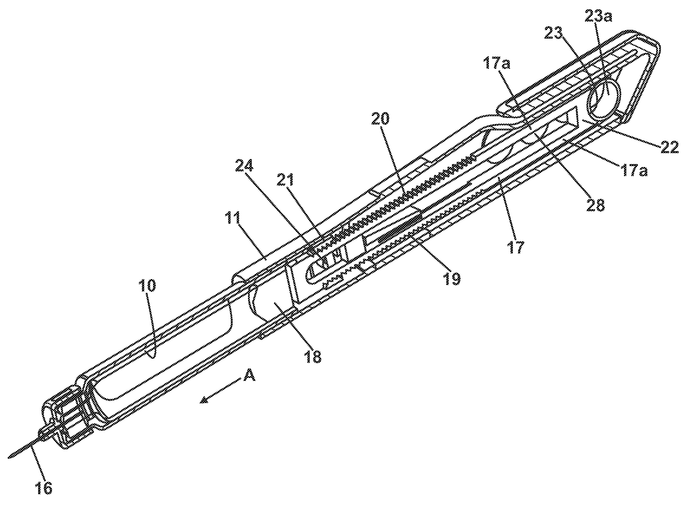
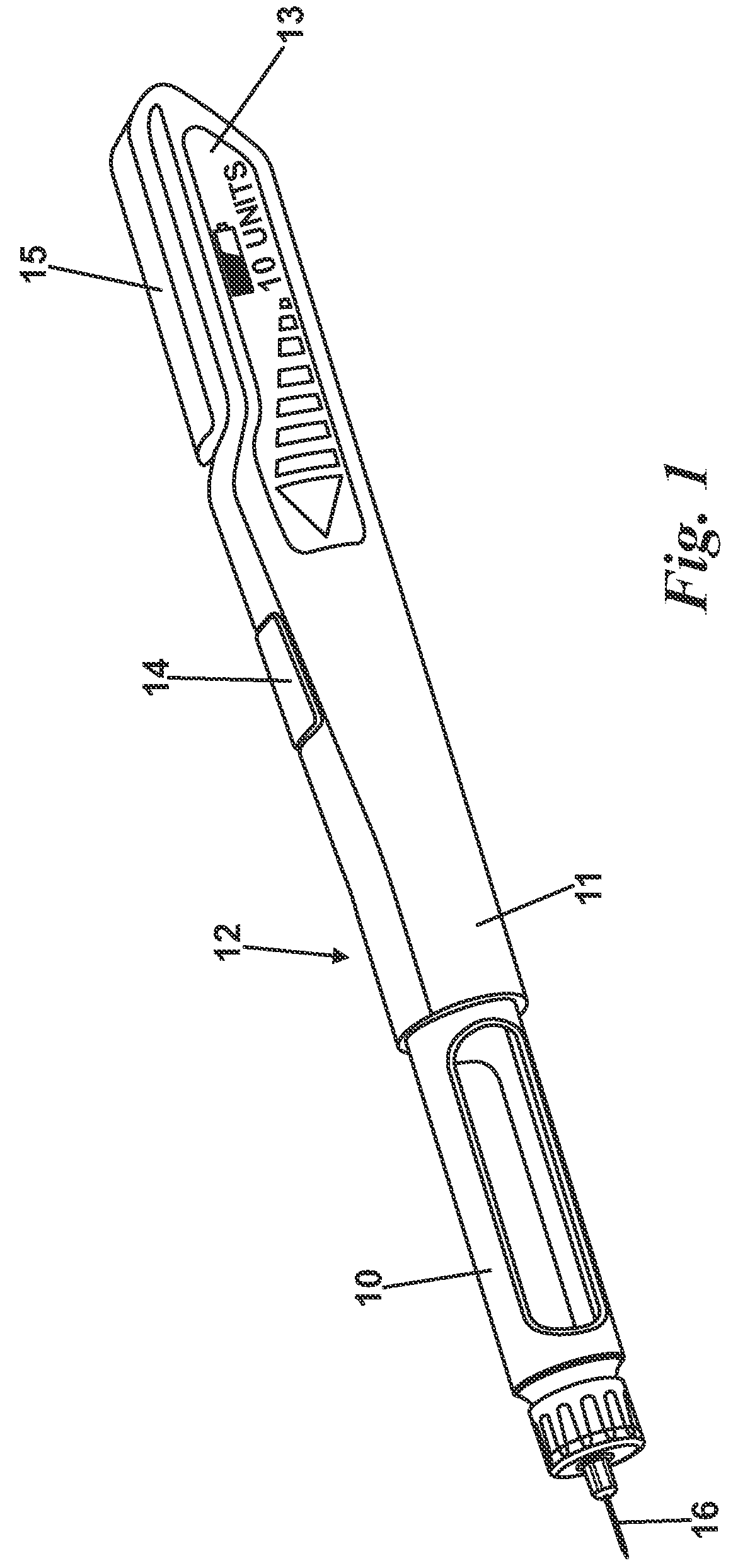
[0026]In FIG. 1 a cartridge 10 is mounted into the barrel 11 of an injector 12. The injector 12 has a touch-sensitive interactive display 13, and a firing or trigger button 14, 15. A hypodermic needle 16 can be mounted on the cartridge 10 in a known manner.

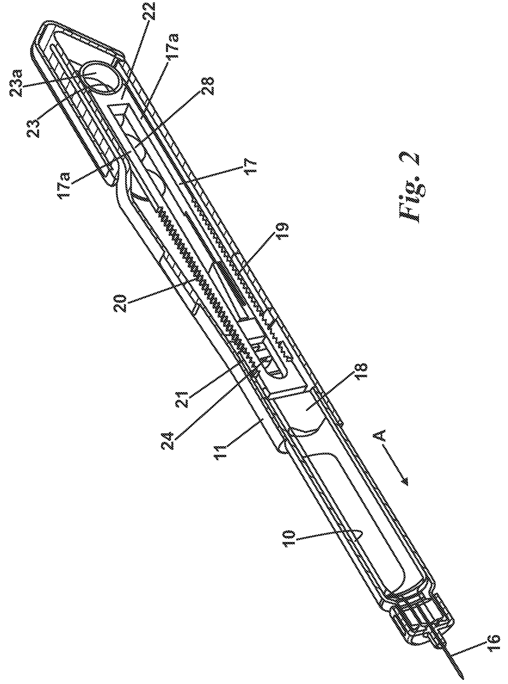
[0027]Turning to FIG. 2, a plunger 17 extends up most of the length of the barrel 11 cooperates with a piston head 18 slideably located within the cartridge 10, when the latter is mounted in the injector 12. As will readily be appreciated, movement of the plunger 17 and hence the piston 18 in the direction A will cause an amount of the drug contained within the cartridge 10 to be expelled from the needle 11.

[0028]The plunger 17 has a pair of elongate struts 17a which carry outwardly facing ratchets having teeth surfaces 19, 20 that engage with corresponding inwardly facing surfaces of an escapement mechanism 21, which will be described in more detail below.

[0029]The struts 17a conjoin at an abutment 22 at the clip end of the barre...


PUM


Abstract

An injector 12 includes a plunger 17 for expelling drugs from a cartridge 10 which can be inserted into the injector 12. An actuator 27 is provided for operating an escapement mechanism 21 to control the movement of the plunger under a drive force and hence the expelled drug.

Description

BACKGROUND OF THE INVENTION[0001]1. Field of the Invention[0002]This invention relates to injectors, such as are used by insulin users.[0003]2. Description of the Related Art[0004]The trend has been to provide those patients who are required to regularly self-inject with automatic injection devices which can provide multiple doses. It is obviously desirable to ensure that the correct dosage volume is delivered each time but the correct dosage volume will vary from patient to patient. It is therefore equally desirable to provide a system which can deliver dose units so that a user can deliver the right number of units for their condition. There are therefore attractions in providing an electronically controlled system but any such system must be fail safe.[0005]Typically injectors are mechanical and work on the basis of a pen like injector into which a disposable drug cartridge can be introduced. The cartridge is arranged to receive a hypodermic needle. With current systems it can be...

Claims


Application Information

Patent Timeline
IPC IPC(8): A61M5/20
CPCA61M5/20A61M5/31595A61M5/2033A61M5/2053A61M5/24A61M2005/2407A61M2005/2488A61M2205/505
Inventor MARSHALL, JEREMYROLFE, STEVEN MARK GUY
Owner OWEN MUMFORD
Learn More