Check patentability & draft patents in minutes with Patsnap Eureka AI!

Constant on-time switching regulator implementing dual control loops

a switching regulator and control loop technology, applied in the direction of electric variable regulation, process and machine control, instruments, etc., can solve the problems of affecting the and reducing the overall efficiency of the switching regulator

Active Publication Date: 2013-07-23
ALPHA & OMEGA SEMICON INC
View PDF8 Cites 11 Cited by
  • Summary
  • Abstract
  • Description
  • Claims
  • Application Information

AI Technical Summary

Benefits of technology

The dual control loop configuration enhances light load efficiency and transient response, maintaining output voltage stability with reduced voltage swings and improved overall efficiency compared to conventional designs.

Problems solved by technology

The conventional switching regulator 10 realizes fast transient response but the efficiency of the regulator is affected by the power loss through the diode.
This power loss reduces overall efficiency of the switching regulator.
However, the efficiency at light load is very poor due to negative current from the inductor L1 flowing into the low-side power switch M2.
However, transient response of the switching regulator circuit 80 is usually very large.
Large voltage spikes at the regulator output voltage when load current changes are undesirable.

Method used


Image

  • Constant on-time switching regulator implementing dual control loops
  • Constant on-time switching regulator implementing dual control loops
  • Constant on-time switching regulator implementing dual control loops

Examples


Embodiment Construction

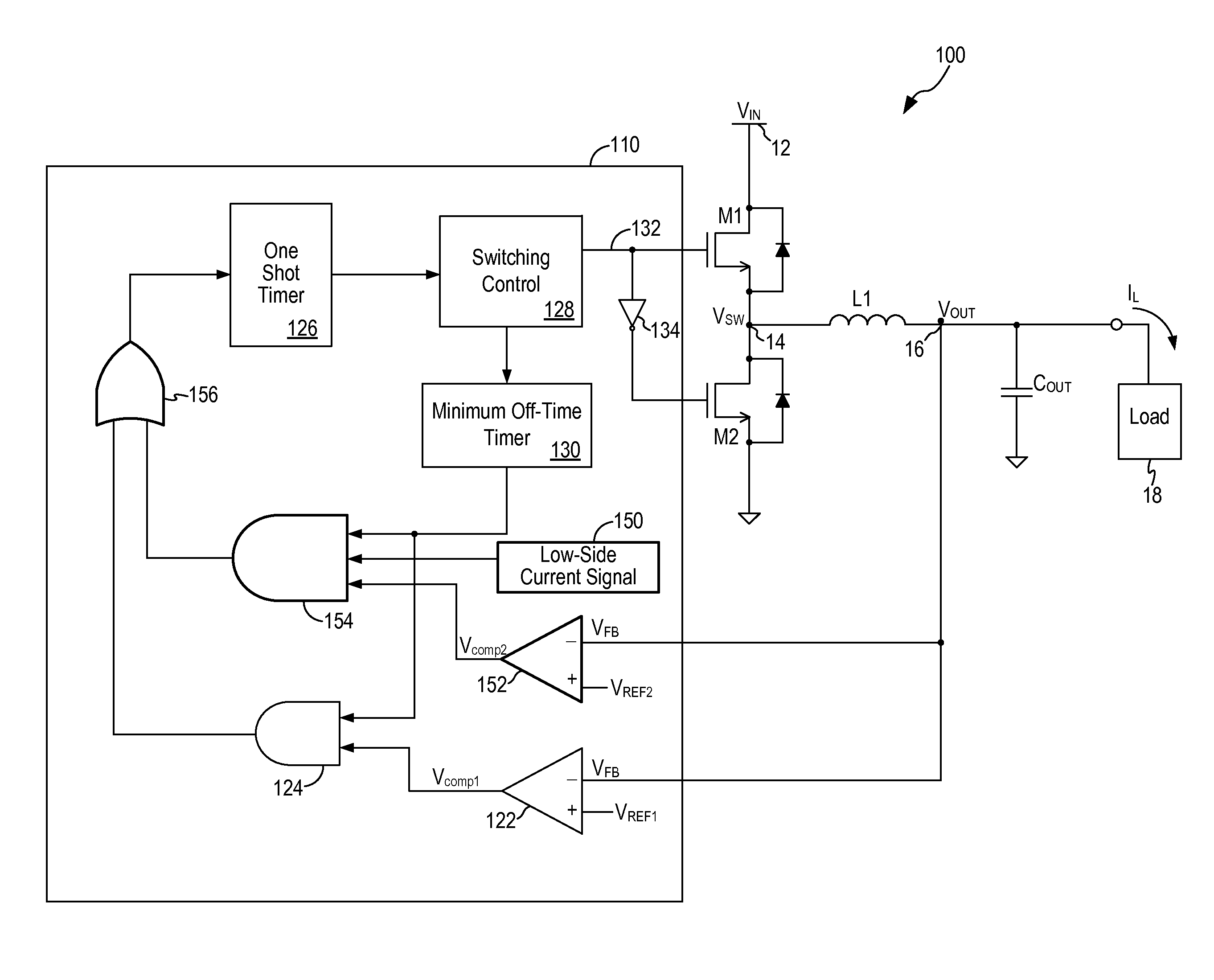
[0019]In accordance with the principles of the present invention, a switching regulator implementing synchronous rectification and a constant on-time control scheme incorporates dual control loops to control the regulated output voltage so as to improve light load efficiency as well as to enhance the transient response. More specifically, the constant on-time switching regulator includes a standard control loop and a light load control loop. The standard control loop operates to regulate the output voltage under the conventional constant on-time control scheme. The light load control loop is activated when light load condition is detected to improve both the light load efficiency as well as ensure fast transient response.

[0020]FIG. 4 is a schematic diagram of a switching regulator implementing synchronous rectification and constant on-time control scheme and incorporating dual control loops according to one embodiment of the present invention. Referring to FIG. 4, a switching regula...


PUM


Abstract

A control circuit for a switching regulator implements constant on-time control scheme with synchronous rectification and applies dual control loops to improve light load efficiency and enhance transient response. In one embodiment, the control circuit includes a first control loop configured to control a one-shot timer to generate a control signal to turn on the main switch when the feedback voltage is below a first reference voltage and a minimum off-time duration has expired. The control circuit further includes a second control loop configured to control the one-shot timer to generate the control signal to turn on the main switch when the feedback voltage is below a second reference voltage and the minimum off-time duration has expired and a low-side current signal has a first state indicative of a light load condition at the output node.

Description

FIELD OF THE INVENTION[0001]The invention relates to switching regulators or DC-to-DC converters and, in particular, to a switching regulator implementing constant on-time control and incorporating a control scheme to improve light load efficiency and enhanced transient response.DESCRIPTION OF THE RELATED ART[0002]DC voltage regulators or switching regulators operate to convert energy from one DC voltage level to another DC voltage level. This type of switching regulators is also referred to as DC / DC converters or switch mode power supplies. A switching regulator provides power supply function through low loss components such as capacitors, inductors, and transformers, and power switches that are turned on and off to transfer energy from the input to the output in discrete packets. A feedback control circuit is used to regulate the energy transfer to maintain a constant output voltage within the desired load limits of the circuit.[0003]A switching regulator can be configured to step...

Claims


Application Information

Patent Timeline
Patent Type & Authority Patents(United States)
IPC IPC(8): G05F1/00
CPCH02M3/1588H02M2001/0032Y02B70/1466Y02B70/16H02M1/0032Y02B70/10
Inventor ZHANG, ZHIYECHANG, KUANG MING
Owner ALPHA & OMEGA SEMICON INC
Features
  • R&D
  • Intellectual Property
  • Life Sciences
  • Materials
  • Tech Scout
  • Unparalleled Data Quality
  • Higher Quality Content
  • 60% Fewer Hallucinations
Learn More