
Radio frequency identification reader antenna having a dynamically adjustable Q-factor

a dynamically adjustable, radio frequency identification technology, applied in the direction of alarms, subscriber indirect connections, sensing record carriers, etc., can solve the problems of not optimizing for each individual function, unable to meet the needs of individual functions, and the design characteristics of antennas must be inevitably compromised, so as to improve the effective bandwidth of tag data reception, improve the efficiency of activation signals, and improve reading distance

Active Publication Date: 2013-07-23
ALLFLEX AUSTRALIA (PTY) LTD
View PDF67 Cites 10 Cited by
  • Summary
  • Abstract
  • Description
  • Claims
  • Application Information

AI Technical Summary

Benefits of technology

The invention relates to systems and methods that use resonant antennas to improve the reading distance of RFID tags. These systems dynamically adjust the Q-factor of the antenna during the tag activation and data transmission intervals to improve the efficiency of the activation signal and expand the antenna's effective bandwidth for tag data reception. This leads to improved reading distance, even when using a fixed frequency activation signal and receiving transponder signals from different standards. Overall, R&D personnel can extract more accurate and reliable information from RFID tags.

Problems solved by technology

However, when a single antenna is used for both transmit and receive purposes, the antenna's design characteristics must be inevitably compromised, and the antenna performs less efficiently than when it can be designed optimally for a single purpose.
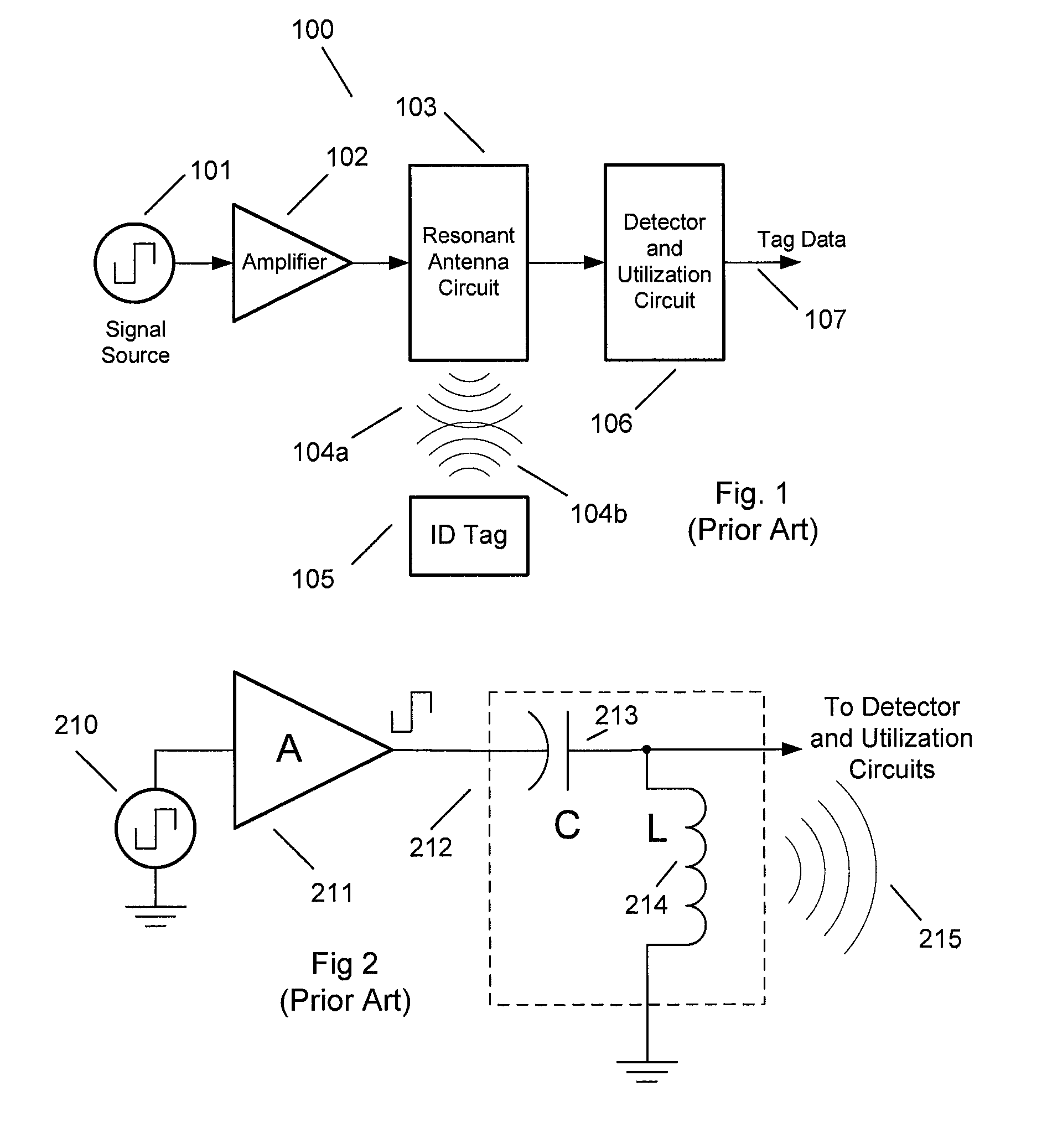
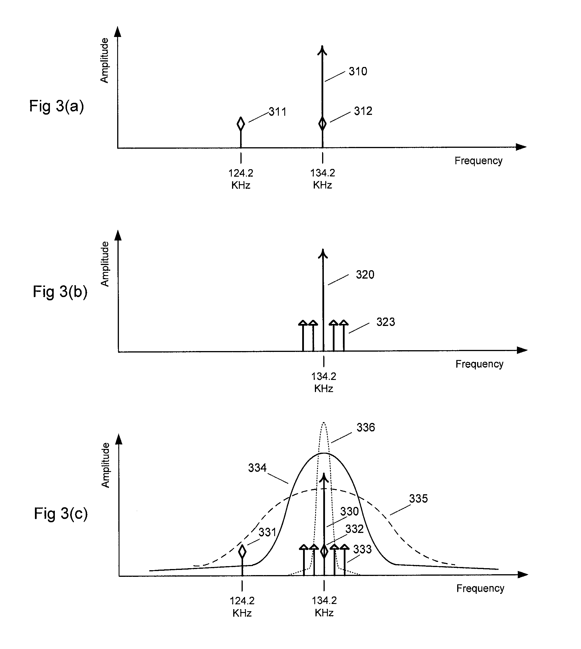
The resulting resonant antenna [212], [335] functions adequately as both transmitter and receiver for HDX and for FDX-B, but in having a fixed Q-factor and a fixed resonant frequency that works for all its functions, it is not optimized for each individual function.
A very high-Q resonant antenna circuit is very effective and efficient for transmitting a single frequency activation signal [330], but has insufficient bandwidth to capture the HDX [331], [332] and the FDX-B [333] transponder spectra.
Thus, a very high-Q antenna typically does not work satisfactorily as both a transmitter and a receiver antenna.
However, the lower HDX data frequency at 124.2 KHz [331] lies outside the antenna's response curve, and typically will not be effectively captured.
If the resonant antenna's Q-factor is decreased even further such that it exhibits the bandwidth depicted by curve [335] in FIG. 3(c), this “low-Q” wide-bandwidth characteristic will adequately capture both the HDX [331], [332] and FDX-B [333] transponder spectra, but the antenna does not transmit the activation signal efficiently.
Furthermore, this wider bandwidth makes the antenna more susceptible to interference signals from other nearby electromagnetic radiating sources, and this can be especially detrimental to FDX-B performance.

Method used


Image

  • Radio frequency identification reader antenna having a dynamically adjustable Q-factor
  • Radio frequency identification reader antenna having a dynamically adjustable Q-factor
  • Radio frequency identification reader antenna having a dynamically adjustable Q-factor

Examples


Embodiment Construction

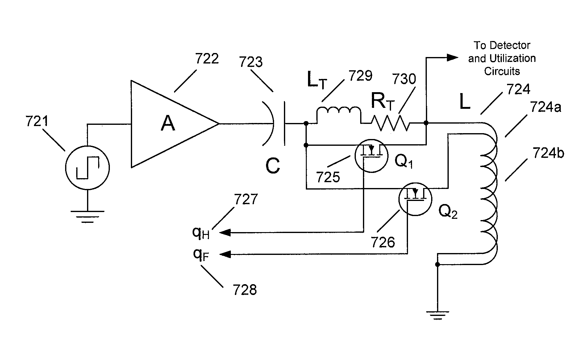
[0056]Turning now to the drawings, systems and methods for reading RFID transponders utilizing readers in which the Q-factor of the resonant antenna of the reader shifts over the course of the reader's interrogation cycle in response to the detection of data from FDX and HDX RFID transponders in accordance with embodiments of the invention are illustrated. In several embodiments, a high Q-factor is used during the transmission of an activation signal and is shifted to a lower Q-factor in response to the detection of data from an FDX tag. In many embodiments, the Q-factor is further reduced during periods in which the activation signal is absent and in which data is detected from an HDX tag. In a number of embodiments, the RFID reader adjusts the Q-factor of its resonant antenna by switching conductors in a multi-filar antenna. In several embodiments, the RFID reader also adjusts the tuning of the resonant antenna during the interrogation cycle. In further embodiments, variations in ...


PUM


Abstract

Turning now to the drawings, systems and methods for reading RFID transponders utilizing readers in which the Q-factor of the resonant antenna of the reader shifts over the course of the reader's interrogation cycle in response to the detection of data from FDX and HDX RFID transponders in accordance with embodiments of the invention are illustrated. One embodiment having a dynamically adjustable Q-factor, wherein the reader transmits an activation signal configured to activate half duplex and full duplex transponders includes a signal source configured to drive a resonant antenna and a dynamic switching circuit configured to set the Q-factor of the resonant antenna to a first value during the transmission of the activation signal. In addition, the dynamic switching circuit is configured to set the Q-factor of the resonant antenna to a second value below the first value during and / or in response to detection of a data signal from a full duplex transponder, the dynamic switching circuit is also configured to set the Q-factor of the resonant antenna to a third value below the second value when the RFID reader is not transmitting the activation signal, and the resonant antenna is multi-filar and the dynamic switching circuit is configured to control the Q-factor of the multi-filar resonant antenna by controlling the filars that are incorporated into the resonant antenna circuit.

Description

CROSS REFERENCE TO RELATED APPLICATIONS[0001]This application claims priority to U.S. Provisional Application Ser. No. 61 / 250,400 filed Oct. 9, 2009, the entirety of which is incorporated herein by reference.FIELD OF THE INVENTION[0002]The present invention relates to radio frequency identification (RFID) systems, and more particularly to RFID readers with resonant antennas.BACKGROUND[0003]Passive low frequency RFID readers and tags use operating principles that are well-know to those of ordinary skill in the art, and that are described in extensive detail in several seminal inventions, including U.S. Pat. No. 1,744,036 to Brard, U.S. Pat. No. 3,299,424 to Vinding, U.S. Pat. No. 3,713,146 to Cardullo, and U.S. Pat. No. 5,053,774 to Schuermann, and in textbooks such as Finkenzeller, “RFID Handbook” (1999).[0004]International Standards Organization (ISO) Standard 11785, “Radio frequency identification of animals—Technical Concept” (1996) defines the technical principles for communicat...

Claims


Application Information

Patent Timeline
Patent Type & Authority Patents(United States)
IPC IPC(8): G08B21/00
CPCG06K7/0008G06K7/10316G06K7/10198
Inventor BATEMAN, LEIGH
Owner ALLFLEX AUSTRALIA (PTY) LTD
Learn More