
Wind turbine siting and maintenance prediction

a technology for wind turbines and maintenance, applied in image data processing, sport apparatus, optimise machine performance, etc., can solve the problems of burdensome sitting of wind turbines and inability to consider maintenance costs

Active Publication Date: 2013-07-30
VESTAS WIND SYST AS
View PDF20 Cites 13 Cited by
  • Summary
  • Abstract
  • Description
  • Claims
  • Application Information

AI Technical Summary

Benefits of technology

The invention provides a visualization tool that allows engineers to see the impact of wind turbines in a specific area. This helps them identify positions where two wind turbines could interfere with each other and cause turbulence. This tool can help avoid expensive calculations and wind tunnel tests. Additionally, it provides an aesthetical understanding of the visual impact of wind turbines.

Problems solved by technology

Siting of wind turbines is burdensome, in particular in respect of on-shore turbines.
However, maintenance costs have hitherto been disregarded when siting wind turbines or wind turbine farms, in spite of the fact that maintenance, including component replacement, presents a significant cost item in wind turbine budgets.

Method used


Image

  • Wind turbine siting and maintenance prediction
  • Wind turbine siting and maintenance prediction
  • Wind turbine siting and maintenance prediction

Examples


example

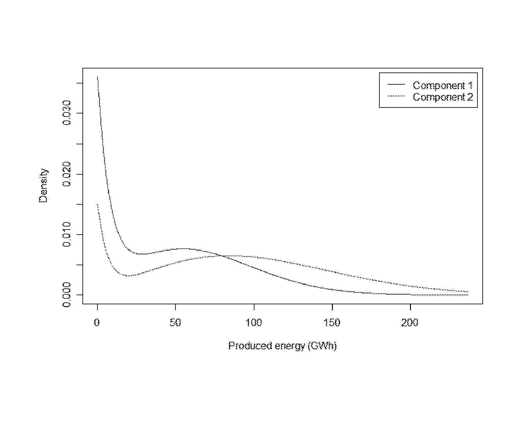
[0068]In the following example only two types of components X1 and X2 are considered, i.e. L=2. The cost prices are for illustration set to c1=600 000 and c2=150 000 . A wind turbine design life time of 20 years is used in the calculations. The probability density functions f1(t) and f2(t) are shown in FIG. 1, showing life time distributions for the two components. Both distributions are obtained as weighted mixtures of exponential distributions and Weibull distributions.

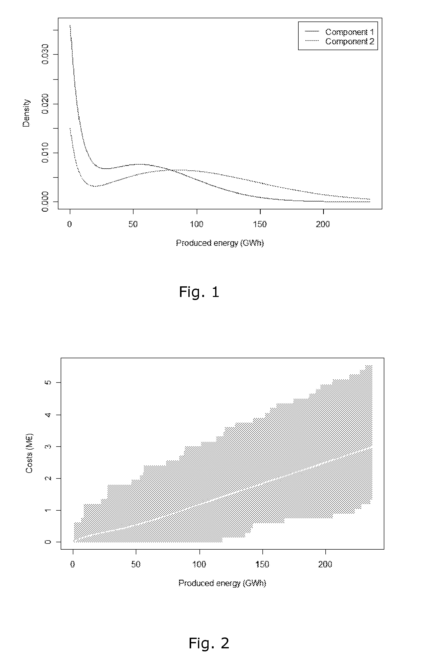
[0069]The total costs are simulated according to the procedure prescribed above using K=10 000 repetitions to obtain the diagram of FIG. 2, showing accumulated expected total costs for one wind turbine as function of produced energy. Imposed is a 95% credible interval for the total cost. It follows from FIG. 2 that when the wind turbine has produced 200 GWh, the expected cost is approximately 2.5 million with an upper 95% credible limit at 5.0 million .

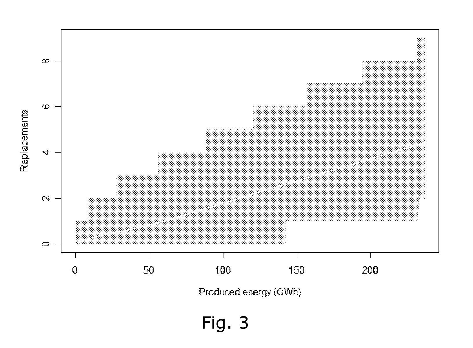
[0070]In a similar the number of component replacements is det...

embodiment 4

5. A computer system , wherein the time-dependent variable is one of: time and accumulated power production of the at least one wind turbine.

6. A computer system according to any of the preceding embodiments, wherein the at least one maintenance parameter is a maintenance parameter of at least one component of the wind turbine.

7. A computer system according to any of the preceding embodiments, further programmed to, during application of said function, to estimate the expected number of replacements of a given wind turbine component during the expected life time of the wind turbine.

8. A computer system according to any of the preceding embodiments, wherein the maintenance parameter includes a maintenance cost expressed as a monetary amount per energy unit produced.

embodiment 8

9. A computer system , wherein the computer system is programmed to compute the maintenance cost as the sum of computed maintenance costs of a plurality of wind turbine components at a given time divided by the accumulated energy produced at that time.

10. A computer system according to any of the preceding embodiments, further programmed to estimate at least one maintenance parameter of a plurality of wind turbines, whereby the computer system is programmed to apply said function to take mutual aerodynamic effects of the wind turbines into account.

11. A method of estimating a maintenance parameter of at least one wind turbine, the method comprising the steps of:[0080]identifying at least one geographical position of the at least one wind turbine;[0081]determining a plurality of wind flow characteristics at the at least one geographical position, said flow characteristics including at least a wind velocity and a turbulence intensity;[0082]defining a function, which expresses said mai...


PUM


Abstract

A computer-implemented method for determining a site for a wind turbine within a confined geographical target region on the basis of an estimate of a maintenance parameter comprises determining a wind climate at the target region, the wind climate including e.g. average wind speed, pre-dominant wind directions, or turbulence intensities. A function expressing the maintenance parameter of the wind turbine as a function of the flow characteristics is defined, and the function is applied to the geographical position to compute an estimated value of the maintenance parameter at that position. Meteorological measurements may be used to obtain the flow characteristics. Wind measurements performed at one location may be numerically extrapolated by numerical methods, e.g. by CFD, to other locations. The maintenance parameter may be expressed as a maintenance risk, number of component replacements, or as a maintenance cost per energy unit. Three-dimensional visualization of wind turbines, e.g. in GoogleEarth™ is further provided by the invention.

Description

PRIORITY CLAIM[0001]This is a U.S. national stage of application No. PCT / EP2008 / 061397, filed on Aug. 29, 2008. Priority is claimed on the following application: PCT Application No. PCT / EP2007 / 059144 Filed: Aug. 31, 2007, the content of which is incorporated here by reference.TECHNICAL FIELD[0002]The present invention relates to the fields of wind turbine siting and wind turbine maintenance prediction. More specifically, the invention provides a computer system and a method for estimating one or more maintenance parameters of a wind turbine, such as component maintenance costs or expected number of component replacements during the life time of the wind turbine. The invention further provides a method for determining a geographical position of a wind turbine. Finally, the invention provides a computer system for providing a three-dimensional visualization of a wind turbine at its intended site.BACKGROUND OF THE INVENTION[0003]Siting of wind turbines is burdensome, in particular in r...

Claims


Application Information

Patent Timeline
Patent Type & Authority Patents(United States)
IPC IPC(8): A63B53/00G06Q10/00G06Q50/00
CPCF03D1/003G06Q10/0637G06Q10/20G06Q50/00G06Q10/10F05B2270/20Y04S10/54Y02E10/72F03D80/50Y04S10/50
Inventor ANDERSEN, KIM EMILCHRISTENSEN, LARS CHRISTIANJORGENSEN, HENRIK KANSTRUP
Owner VESTAS WIND SYST AS
Learn More