Recoil system for firearms

a recoil system and firearm technology, applied in the field of recoil simulation devices, can solve the problems of high construction cost, increased operation duration, and increased cost, and achieve the effect of reliable device operation

Active Publication Date: 2013-07-30
RAUSER WILLI
View PDF7 Cites 2 Cited by
  • Summary
  • Abstract
  • Description
  • Claims
  • Application Information

AI Technical Summary

Benefits of technology

[0013]In case of corresponding design of the pressure valve and of the discharge valve—for example in the form of nonreturn valves—as well as the ducting of pertinent connecting channels, the entire hydraulic fluid may again be conveyed back into the hydraulic chamber by resetting the adjusting piston in the return chamber from its end position into its initial starting position. The device is again “loaded” and can be used again in the firearm for discharge of the next “series of shots.” Due to this “loading process” by means of simple pushing back of the adjusting piston in the return chamber, extremely short “loading times” can be achieved, such that the device can be kept ready for operation on site for multi-use without great expense.
[0014]Based on the embodiment according to the present invention, extremely high acceleration values of the breechblock can be achieved, so that a realistic recoil simulation can be achieved. In the device according to the present invention, furthermore, a fully closed pressure system is used, and no fluid is discharged outwards, so that this device can be used absolutely without risk for recoil simulation.
[0017]Furthermore, provisions may also be made for the pressure valve to have a tappet, via which a valve ball of the pressure valve can be brought from its closed position into its open position, and that the tappet can be adjusted by a drag lever, whose adjusting movement is brought about by the valve pressure lever in its active, deflected working position. By means of the drag lever provided, when the tappet is pressed down and released, lateral forces and greater frictional forces caused thereby are avoided or are at least reduced to the extent that both the tappet and the valve pressure lever have an as low as possible amount of wear.
[0022]Various feature combinations taken alone by themselves or in different combinations with one another as well, for a more reliable operation of the device according to the present invention, are highly advantageous for recoil simulation. However, especially the mechanical functional components, which are embodied here essentially as levers, are also partly embodied in the form of slider controls. This is especially conceivable when the working piston, with sufficient installation space, acts on the breechblock immediately directly with an adjusting force.

Problems solved by technology

However, this mechanism only permits a trigger resistance, which does not correspond to the actual conditions of the different types of guns and therefore in practice is perceived as insufficient.
Moreover, the prior-art recoil system requires an entire new construction or a reconstruction of prior-art pistols, which is extremely expensive in terms of construction and hence cost-intensive, wherein economic reconstruction is not possible or is ruled out to a large extent.
Here it is found that because of the decreasing gas pressure in the compressed gas cartridge, the recoil simulation is weakened with increasing duration of the operation.
Moreover, only an expensive replacement or an expensive refilling is possible after the compressed gas cartridge is used up.
Further, it has been found that in systems of this type, which operate with compressed gas cartridges for “recoil simulation,” the gun may cool off due to the essentially abrupt expansion of the gas.
Especially when used in automatic guns with rapid firing sequence, it has been found that the gun may even “freeze up” after discharge of several volleys, such that the recoil system is put out of operation.
Moreover, the compressed gas is discharged outwards, which is likewise undesirable.

Method used


Image

  • Recoil system for firearms
  • Recoil system for firearms
  • Recoil system for firearms

Examples


Embodiment Construction

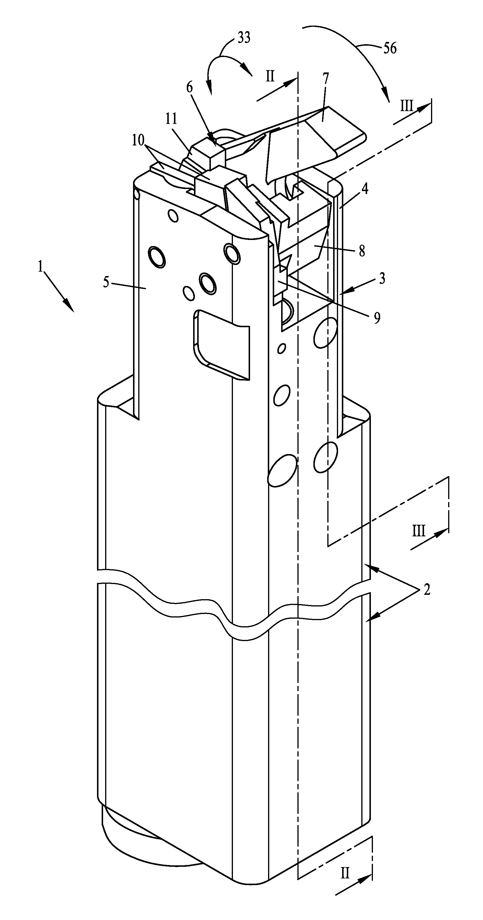
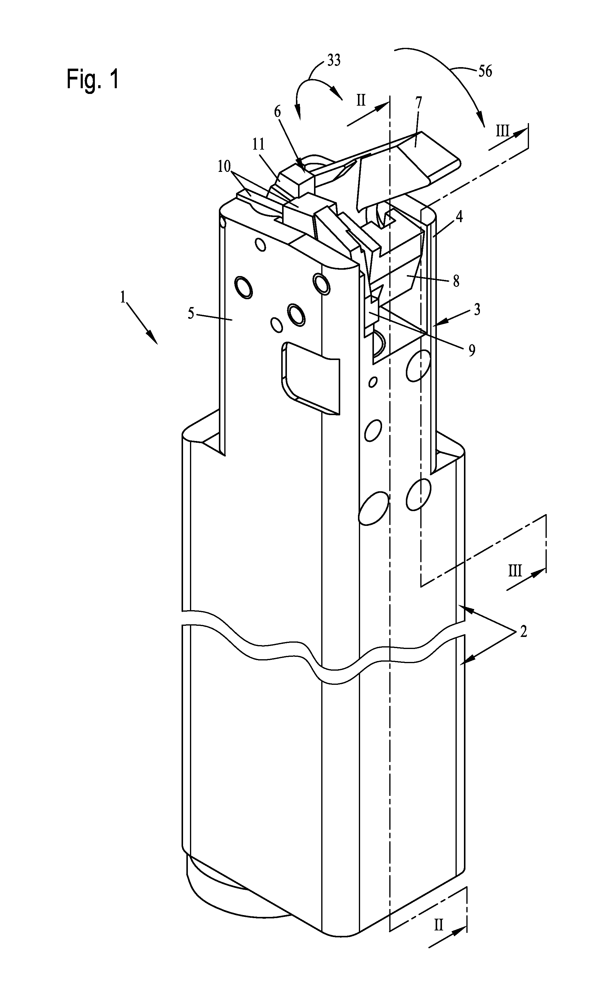
[0036]Referring to the drawings in particular, FIG. 1 shows a perspective view of an embodiment variant of a device according to the present invention, which in the present exemplary embodiment has a housing 2. In the upper end range, this housing 2 forms a control head 3, which, in the upwards direction, forms two mounting walls 4 and 5 running parallel to one another and spaced apart from one another. A control mechanism 6, which in the present embodiment variant especially has a pivotably mounted recoil lever 7, is mounted between these mounting walls. FIG. 1 shows the recoil lever 7 in its released, active working position. This recoil lever 7 is used for the abrupt adjusting of a breech head of a firearm, as will be explained in detail later. This recoil lever 7 is deflected by a hydraulically actuatable working piston.

[0037]Furthermore, FIG. 1 also partly shows a breech catch 8, a catch lever 9, a spring-loaded bearing 10 as well as a pressure lever 11, whose mode of operation...


PUM


Abstract

A device (1) simulates the recoil of a firearm and has a breechblock (60) with a knockover slide (63). To avoid freezing up and outward emissions, a control mechanism controls a hydraulic working piston in working connection with the breechblock (60). A valve pressure lever (11) is deflected by movement of the knockover slide (63) to open a pressure valve (20), as a result of which fluid is fed to the working piston. The valve (20) has a movable separating piston (14) separating a hydraulic chamber (13) tightly from a gas chamber (17) filled with compressed gas. The separating piston (14) is acted on by the compressed gas. The working piston at the end of an adjusting movement brings about the closing of the valve (20) and opening of a discharge valve. The hydraulic fluid is guided, with open discharge valve, from the working piston into a return chamber (24).

Description

CROSS REFERENCE TO RELATED APPLICATIONS[0001]This application claims the benefit of priority under 35 U.S.C. §119 of German Utility Model DE 20 2010 006 430.9 filed May 4, 2010, the entire contents of which are incorporated herein by reference.FIELD OF THE INVENTION[0002]The present invention pertains to a device for the simulation of the recoil of a firearm, which is retrofitted as a laser gun for training purposes and has a breechblock with a knockover slide which can be moved backwards and forwards between a closed starting position and an open end position.BACKGROUND OF THE INVENTION[0003]Laser guns of the type of this class are known, for example, from WO 98 / 14745. A recoil system for guns with installed laser for “sharp-shooting simulation” is described there. A specially made mechanism is used for triggering the recoil system. However, this mechanism only permits a trigger resistance, which does not correspond to the actual conditions of the different types of guns and theref...

Claims


Application Information

Patent Timeline
Patent Type & Authority Patents(United States)
IPC IPC(8): F41A33/00
CPCF41A33/06
Inventor RAUSER, WILLI
Owner RAUSER WILLI
Why Eureka
Try Eureka