Optical parametric oscillator with optimized output coupling

an optical parametric oscillator and output coupling technology, applied in the field of optical communication, can solve the problems of non-optimal output coupling, wavelength dependence of extracted output power, and elaborate designs

Inactive Publication Date: 2013-07-30
FUNDACIO INST DE CIENCIES FOT NIQUES +1
View PDF6 Cites 7 Cited by
  • Summary
  • Abstract
  • Description
  • Claims
  • Application Information

AI Technical Summary

Benefits of technology

[0012]The current invention solves the aforementioned problems by disclosing a stable optical parametric oscillator (OPO), in which the usual scheme of a nonlinear crystal pumped by a laser source, and an optical resonator, is improved by including an interferometer integrated in the resonant cavity. The interferometer acts as an output coupler, determining the level of coupling of the output signal and allowing optimization of the output power level.
[0013]Preferably, the interferometer is an antiresonant ring (ARR) interferometer, which results in a higher stability and a wider wavelength range. Nevertheless, the OPO can be implemented using alternative interferometers, such as Michelson, Fabry-Perot or Mach-Zehnder.

Problems solved by technology

Many OPOs are known, such as those disclosed in US 2007 / 0291801A1 or US2005 / 0243876 A1, but in many cases they suffer from elaborate designs, non-optimum output coupling, and wavelength dependence of extracted output power.

Method used


Image

  • Optical parametric oscillator with optimized output coupling
  • Optical parametric oscillator with optimized output coupling
  • Optical parametric oscillator with optimized output coupling

Examples


Embodiment Construction

[0037]The matters defined in this detailed description are provided to assist in a comprehensive understanding of the invention. Accordingly, those of ordinary skill in the art will recognize that variation changes and modifications of the embodiments described herein can be made without departing from the scope and spirit of the invention. Also, description of well-known functions and elements are omitted for clarity and conciseness.

[0038]Note that in this text, the term “comprises” and its derivations (such as “comprising”, etc.) should not be understood in an excluding sense, that is, these terms should not be interpreted as excluding the possibility that what is described and defined may include further elements, steps, etc.

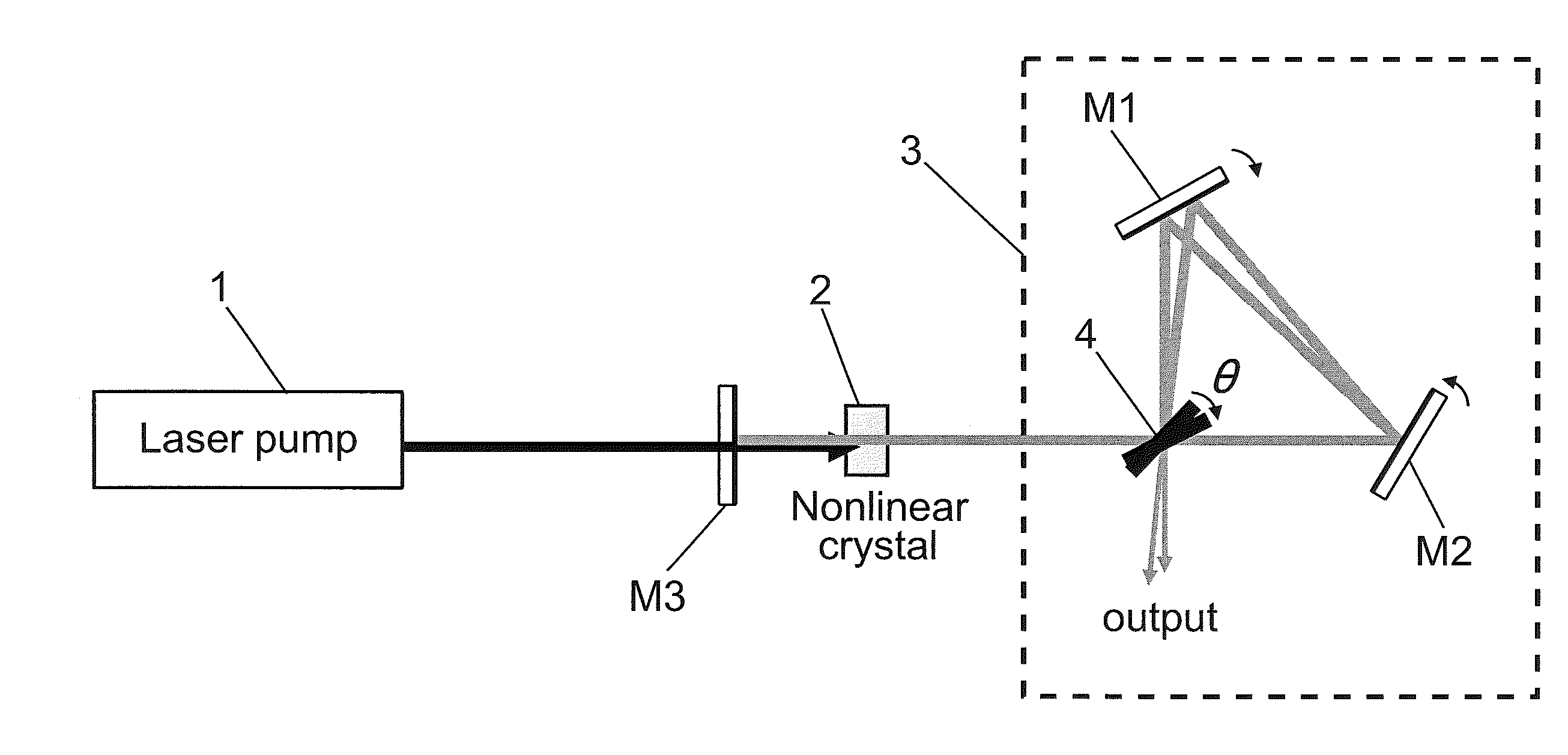
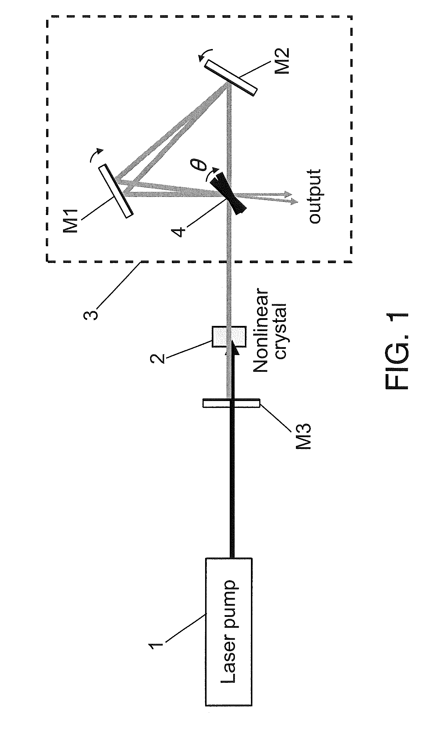
[0039]FIG. 1 shows the architecture of an OPO according to a preferred embodiment of the present invention. The OPO comprises a laser source 1, which pumps a nonlinear crystal 2. The nonlinear crystal converts the input laser wave into two output waves of low...


PUM

PropertyMeasurementUnit
transmittanceaaaaaaaaaa
reflectanceaaaaaaaaaa
frequencyaaaaaaaaaa

Abstract

An optical parametric oscillator including a nonlinear crystal pumped by a laser source and an optical resonator, including an optical interferometer, which determines a level of output coupling of the oscillator, allowing high stability, broad wavelength tuning, and output power level optimization.

Description

TECHNICAL FIELD[0001]The present invention has its application within the optical communication sector and, especially, in the industrial area engaged in providing optical oscillators.BACKGROUND[0002]An antiresonant ring interferometer (ARR) is an optical interferometer in which a beamsplitter (BS) separates an input beam (Ein) into two beams (clockwise and counter clock-wise). After propagation inside the ring, and transmission or reflection by the beamsplitter again, the new pairs of fields interfere, giving rise to the final reflected and transmitted output fields (Er and Et).[0003]The ARR can be treated mathematically as a 4-port optical splitter whose transfer matrix is given by[0004]MARR=⌊tr-rt⌋,where r and t are the amplitude reflectance and transmittance, respectively. Moreover, as two of the ports are connected by the ring, the reflected and transmitted fields from the ARR are given by[0005]⌊ErEt⌋=MARR2⁢⌊E2E1⌋.[0006]In the particular case where[0007]⌊E2E1⌋=⌊0Ein⌋,then⁢⁢⌊ErE...

Claims


Application Information

Patent Timeline
Patent Type & Authority Patents(United States)
IPC IPC(8): G02F1/39
CPCG02F1/39
Inventor ESTEBAN-MARTIN, ADOLFOEBRAHIM-ZADEH, MAJID
Owner FUNDACIO INST DE CIENCIES FOT NIQUES
Why Eureka
Try Eureka