
Floor covering

Active Publication Date: 2013-08-06
SCHULTE GUIDO
View PDF24 Cites 16 Cited by
  • Summary
  • Abstract
  • Description
  • Claims
  • Application Information

AI Technical Summary

Benefits of technology

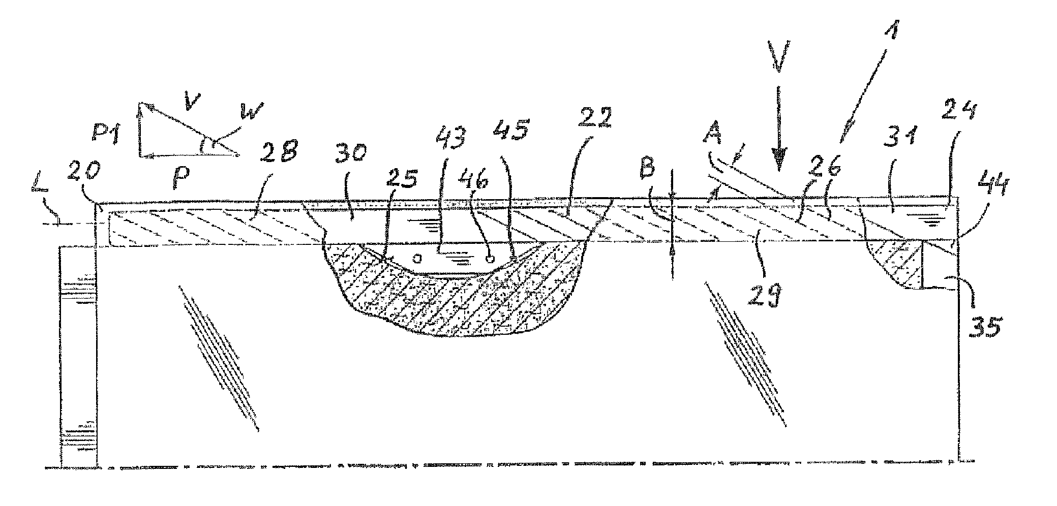
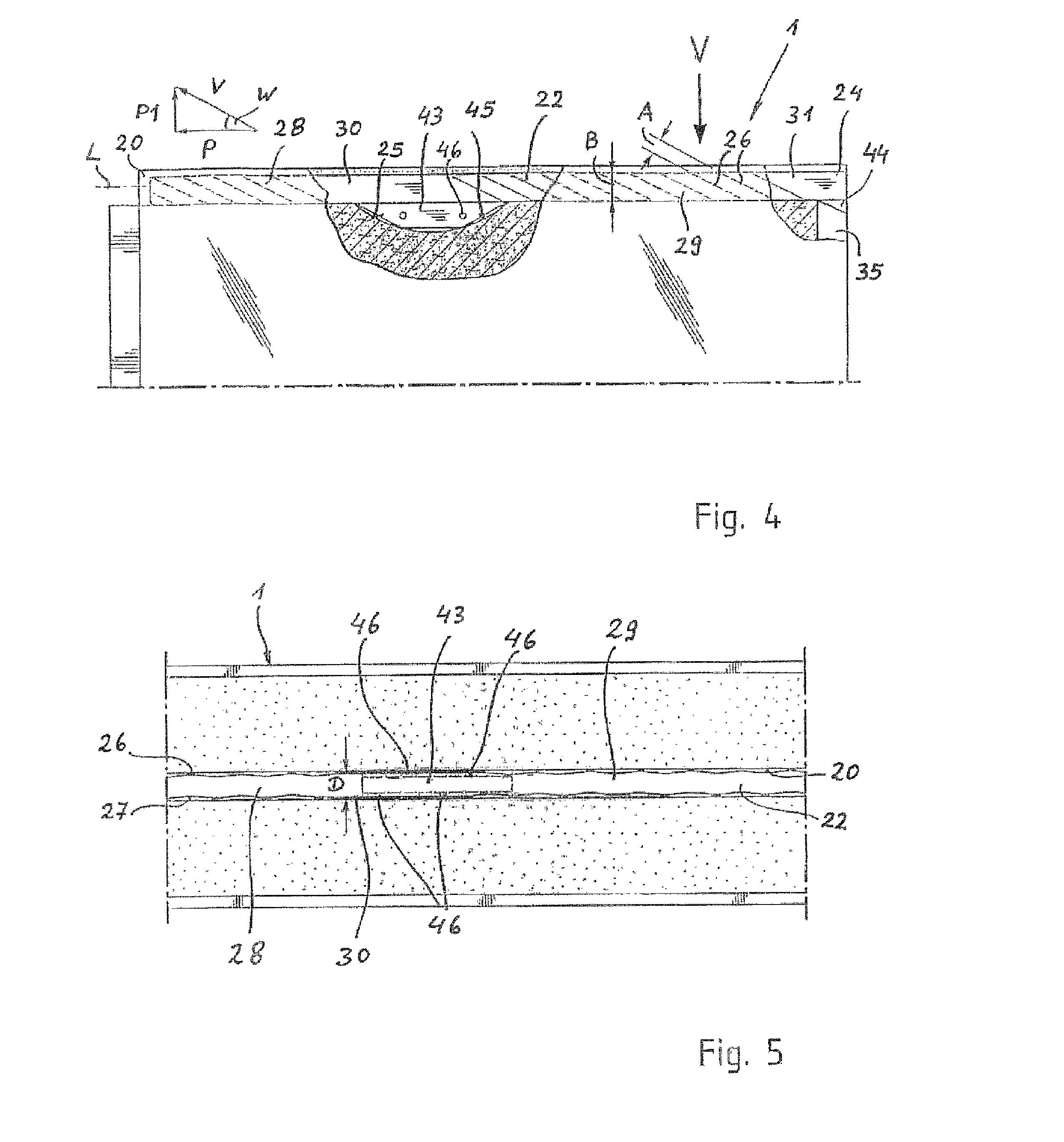
The invention relates to a new design of a head spring for vehicle panels. The head spring is designed to fit snugly into a groove in the panel and has non-undulated regions which are easy to move. The ratio of undulated to non-undulated regions should be at least 2:1. By angling the wave crests and wave troughs in the recess and cam, the head spring can move more easily and comes into contact with a smaller number of surface regions, making it easier to select tighter tolerances between the groove and the spring. This design produces a more improved installation without making it more difficult.

Problems solved by technology

As a result, the head spring has over its entire length a relatively elastic characteristic, which means that the head spring can be easily moved, but also springs back under load, which can cause an undesirable height offset wherein adjacent panels are subjected to different loads.
Advantageously, the sides of the non-undulated regions may be limited so that the head spring remains easily displaceable.

Method used


Image

  • Floor covering
  • Floor covering
  • Floor covering

Examples


Embodiment Construction

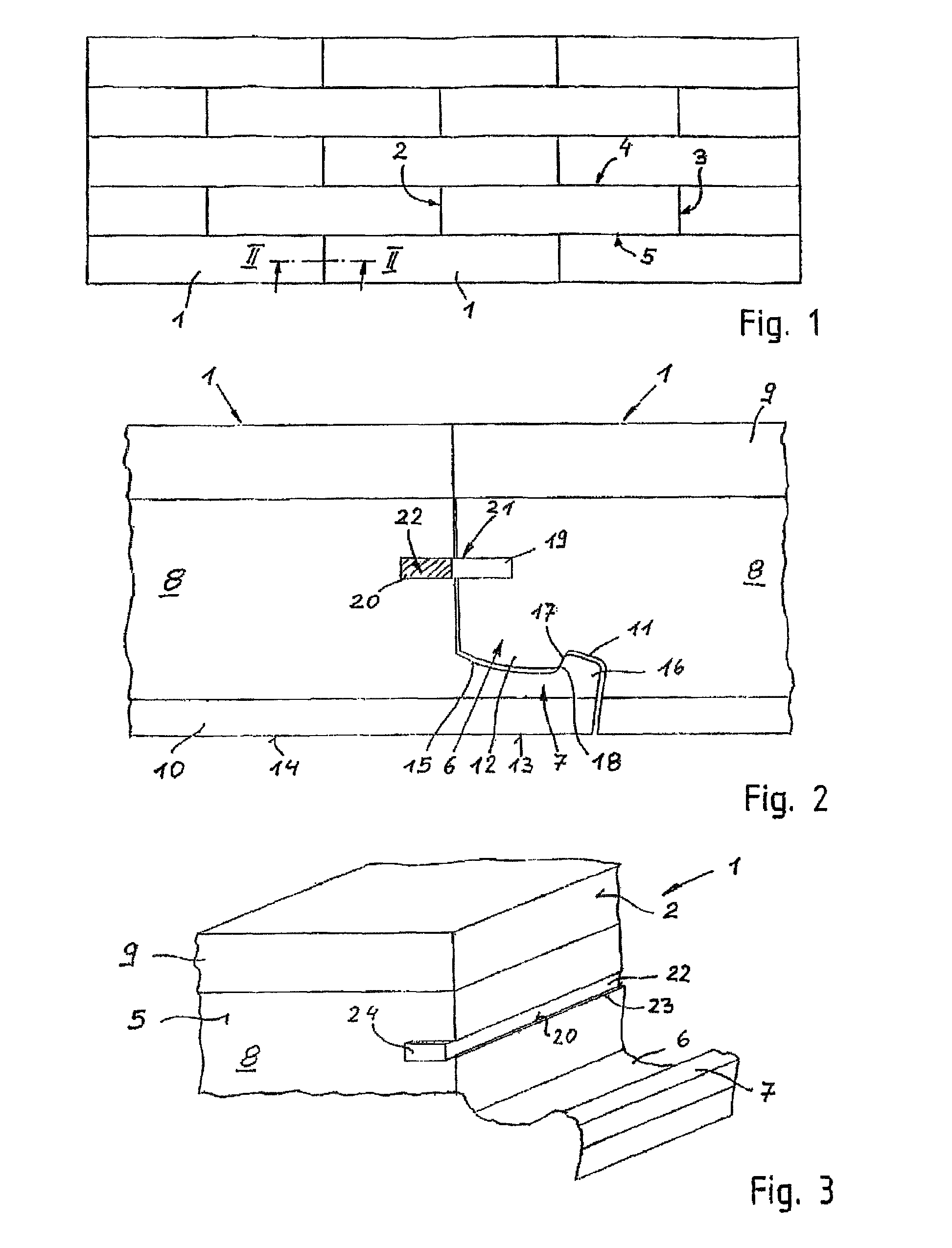
[0025]FIG. 1 shows a floor covering made of the plurality of interlocked rectangular panel elements 1. The panel elements 1 have locking rails on their respective head sides 2, 3 and on their respective longitudinal sides 4, 5. The locking rails of adjacent panels in the covering engage with each other in the installation position.

[0026]FIG. 2 shows locking rails 6, 7 on the head sides 2 and 3, respectively, of a panel element 1. FIG. 2 shows a vertical cross-section through the head-side joint region between two panel elements 1, when viewing the connection at the head sides 2, 3. The unillustrated locking rails on the longitudinal sides of a panel element 1 may be configured different from the locking rails 6, 7.

[0027]A panel element 1 is made of a support layer 8 made of fiber material, typically a highly or moderately compacted fiber plate, wherein the support layer 8 has a top-side cover layer 9 and a bottom-side back pull 10. The cover layer may be made from a decorative paper...


PUM


Abstract

Disclosed is a floor covering consisting of a plurality of panel elements (1) that can be laid in combination with each other. On the front sides (2, 3) and longitudinal sides (4, 5), the panel elements have locking strips (6, 7) that engage with each other in the assembled position in a covering in which panel elements (1) adjoin each other. The front sides (2, 3) of the panel elements (1) have grooves (19, 20). The grooves (19, 20) of two abutting front sides (2, 3) are aligned and form a locking channel (21) for accommodating a front spring (22) that is pre-assembled in one of the grooves (20). The front spring (22) projects from an end of the groove (20) that faces the longitudinal side (5) of the panel element (1) and can be moved in part from one groove (20) into the corresponding groove (19) of the adjoining panel element (1) by sliding the projecting end (24) of the front spring (22) into the groove (20). The groove (20) that accommodates the front spring (22) has at least one recess (45) within which the stop surface (25) is formed and into which a cam (43) of the front spring (22) engages. The front spring (22) has a wavy shape. The wavy sides of the front spring (22) face a decorative side and a bottom side of the panel elements (1). The front spring (22) should have at least one non-wavy zone (30) that is located between two wavy zones (28, 29), at a distance from the ends (24) of the front spring (22).

Description

CROSS-REFERENCES TO RELATED APPLICATIONS[0001]This application is the U.S. National Stage of International Application No. PCT / DE2009 / 001229, filed Sep. 1, 2009, which designated the United States and has been published as International Publication No. WO 2010 / 028623 and which claims the priority of German Patent Application, Serial No. 10 2008 047 098.8, filed Sep. 12, 2008, pursuant to 35 U.S.C. 119(a)-(d).BACKGROUND OF THE INVENTION[0002]The invention relates to a floor covering composed of interlocked panel elements.[0003]According to WO 2008 / 017301 A2, floor coverings made of a plurality of interconnected panel elements, which have interlocking rails at their head sides and the longitudinal sides engaging in the installed position with adjacent panel elements of a floor covering are known in the art. Grooves are provided in the head sides, wherein the grooves of two abutting head sides correspond with each other and form a locking channel for receiving a head spring. The head s...

Claims


Application Information

Patent Timeline
IPC IPC(8): E04B2/00
CPCE04F15/02E04F2201/0169E04F2201/0523Y10T403/76E04F2201/0547Y10T403/589E04F2201/0541F16B2200/73
Inventor SCHULTE, GUIDO
Owner SCHULTE GUIDO
Learn More