Method for manufacturing aphakic intraocular lens

a manufacturing method and technology for intraocular lenses, applied in the field of methods, can solve the problems of insufficient improvement of vision, insufficient use of bifocal intraocular lenses that adopt a conventional diffractive lens structure, and inability to achieve effective vision, etc., to achieve secure the allocation of 0th order light and reduce the intensity of unnecessary nth order light such as the second order light

Active Publication Date: 2013-08-06
MENICON CO LTD
View PDF14 Cites 21 Cited by
  • Summary
  • Abstract
  • Description
  • Claims
  • Application Information

AI Technical Summary

Benefits of technology

[0009]With the foregoing in view, it is accordingly an object of the present invention, to provide a novel method of manufacturing an aphakic intraocular lens that is capable of ensuring every multi-focusing effect more securely, while reducing the impact of pupil shrinkage and lens eccentricity.

Problems solved by technology

This consequently causes problems such as refractive disorders including myopia, hyperopia and presbyopia, or even cataract and the like, which makes it hard to obtain effective vision.
However, since the intraocular lenses that have been conventionally used are monofocal ones, the problem is that the eye function ends up with no focal adjustment, although the vision is restored after the eye surgery.
However, it is increasingly recognized in recent years that a bifocal intraocular lens that adopts a conventional diffractive lens structure is not sufficient enough to improve vision.
That is, in case of an intraocular lens that adopts the diffractive lens structure described in the above Patent Document 1, for example, the 0th order light and first order diffracted light are assigned for far vision and near vision respectively, which revealed a problem that allocating energy to the mid-section between the 0th order light and first order diffracted light becomes more difficult and the contrast in the intermediate vision range gets too low.
However, the intraocular lens described in Patent Document 2 had a risk of failing to achieve the desired focal effect when the diameter of incident light beam varies in cases such as pupil shrinkage.
In addition, even if the design of the lens is based on a consideration of physiological pupil diameter, it is not necessarily possible to insert an intraocular lens in the desired position relative to the pupil and keep it stable therein, which poses a risk of failing to achieve the desired focal effect due to the eccentricity of the lens.Patent Document 1: U.S. Pat. No. 5,121,980Patent Document 2: U.S. Pat. No. 7,188,949

Method used


Image

  • Method for manufacturing aphakic intraocular lens
  • Method for manufacturing aphakic intraocular lens
  • Method for manufacturing aphakic intraocular lens

Examples


first embodiment

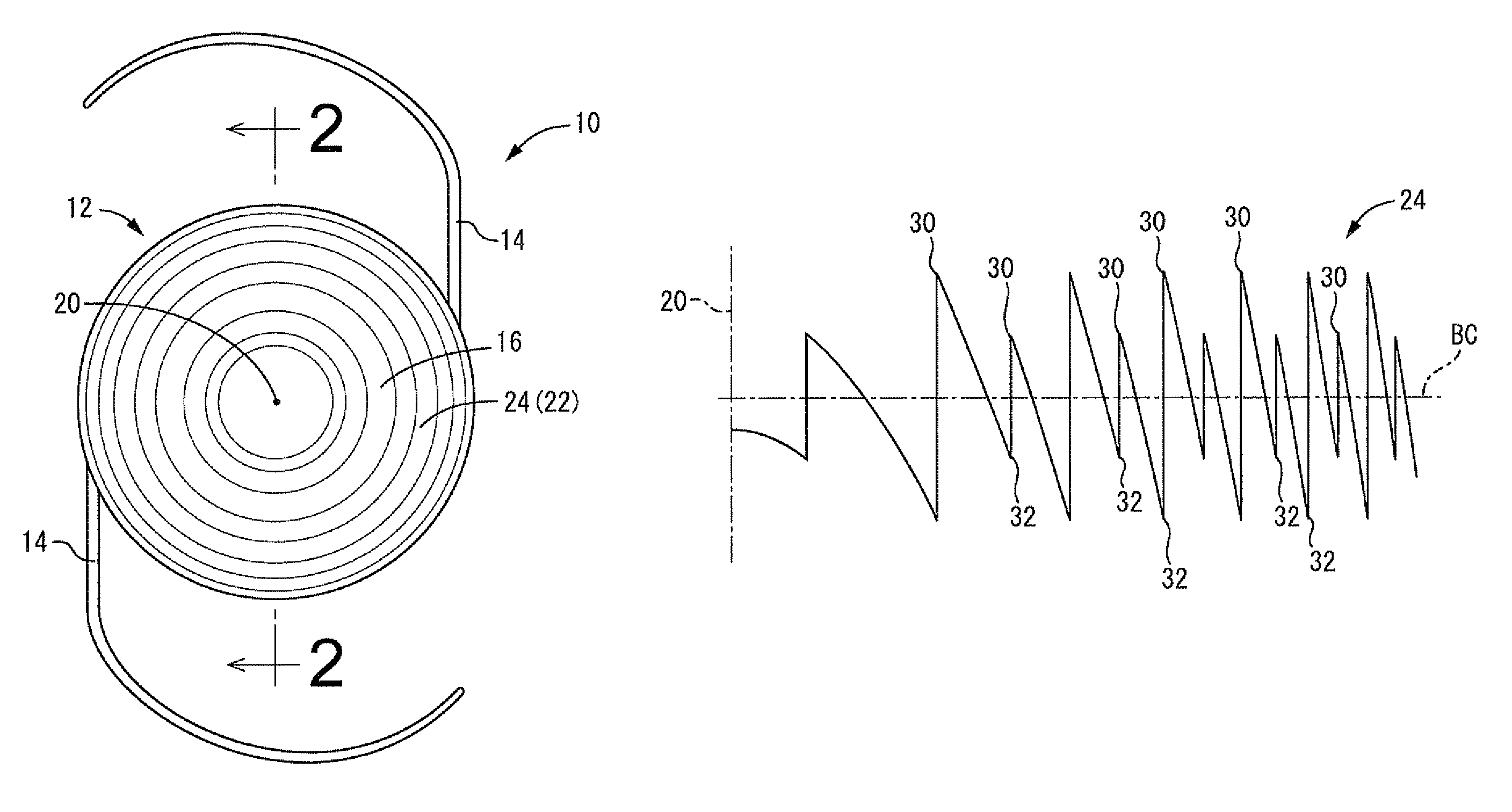
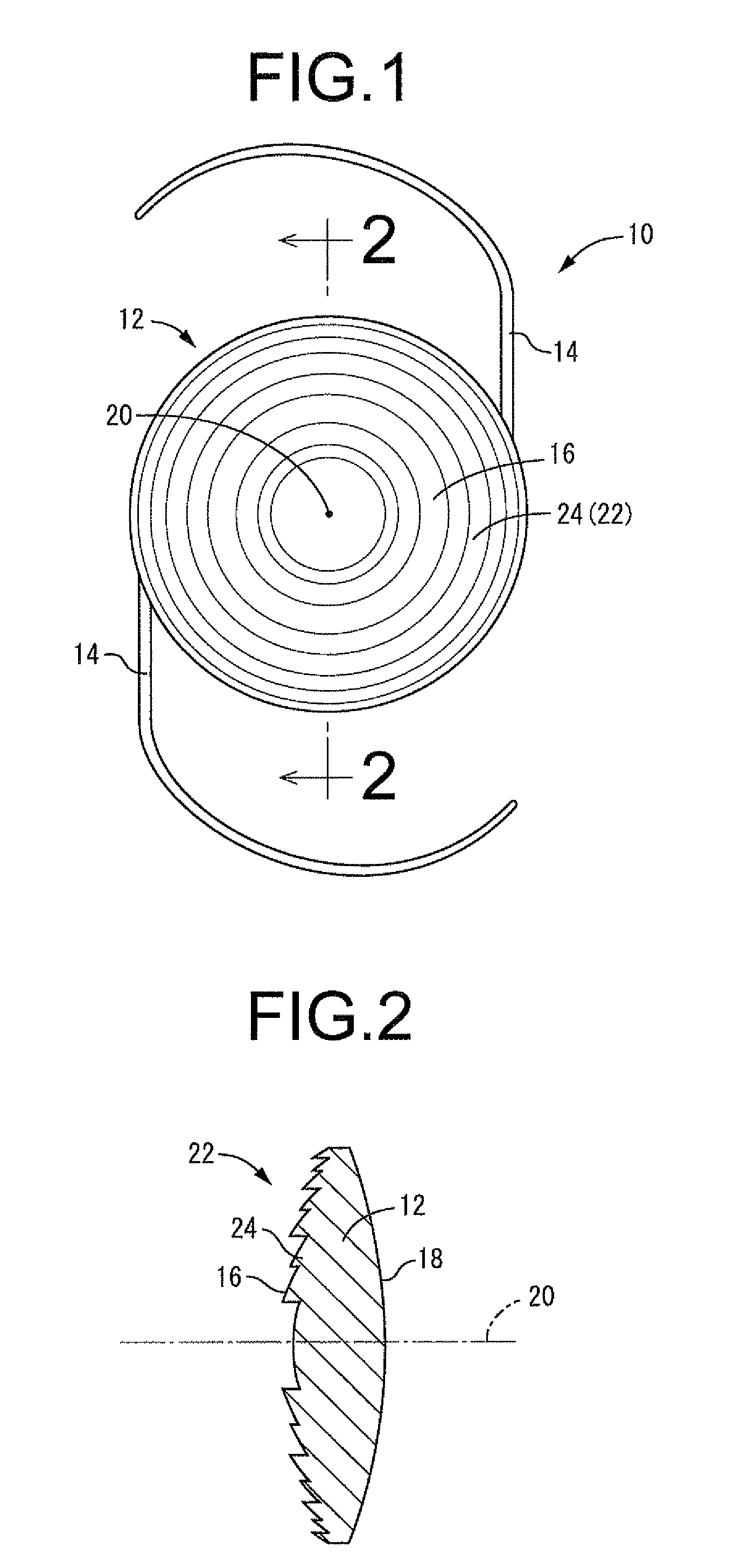
[0096]First of all, FIG. 1 shows a front view diagram of an intraocular lens 10 as a first embodiment related to the aphakic intraocular lens in this invention, and FIG. 2 shows a cross-section diagram of an optical part 12 of said intraocular lens 10 described later. Here in FIGS. 1 and 2, a relief pattern 24 described later is shown with its size exaggerated for better understanding.

[0097]The intraocular lens 10 comprises the optical part 12 that is part of the lens main body and gives optical properties of the intraocular lens 10 and a pair of haptics 14 that extend out from the optical part 12. The optical part 12 comprises an optical front surface 16 in an approximate convex shape of a sphere as a whole, and an optical rear surface 18 in also an approximate convex shape of a sphere as a whole. And, the optical part 12 is, in its entirety, in an approximate shape of a disc with the thicker center, and is formed as a solid of revolution formed around a geometric lens center axis ...

second embodiment

[0147]First, FIG. 11 shows a relief profile of a relief pattern 50 as this invention. In the present embodiment, a synchronous structure where two reliefs with the dioptric power at +3.0D for near vision and the other at +1.0D for intermediate vision are periodically overlapped. By the way, the relief profile of the present embodiment is the one obtained under the following settings:

Radius of the base curve of the optical front surface 16=8.000 mm

Dioptric power of the optical part 12=+25.0D

Refractive index of the lens material=1.500

Refractive index of the surrounding medium=1.336

Designed wavelength=500 nm

Zone constant of the relief for near vision ‘a’=1

[0148]Meanwhile, the grating pitch is larger in the relief for intermediate vision than in the relief for near vision.

[0149]Especially in the present embodiment, two relief depths of the relief for near vision are provided per each zone of the relief for intermediate zone, and these three zones in total are formed, that is, in one out...

third embodiment

[0152]Next, FIG. 13 shows a relief profile of a relief pattern 60 as this invention. In the present embodiment, a synchronous structure where two reliefs with the dioptric power at +3.0D for near vision and at +1.0D for intermediate vision are periodically overlapped. Meanwhile, the grating pitch is larger in the relief for intermediate vision than in the relief for near vision.

[0153]In the present embodiment, two relief depths of the relief for near vision are provided per each zone of the relief for intermediate zone, and these three zones in total are formed, that is, in one out of three zone radii of the relief for near vision, the zone radius of the relief for intermediate vision is made equal to that of the relief for near vision. In each zone of the relief for intermediate vision composed of an overlap of reliefs for near vision, the height of the relief depth of the relief for near vision located between the relief depths of the relief for intermediate vision relative to the...


PUM


Abstract

A method of manufacturing an aphakic intraocular lens that is capable of ensuring every multi-focusing effect more securely, while reducing the impact of aperture changes and lens eccentricity. At least two reliefs whose first order diffracted lights give respective focal distances different from one another are set to overlap with each other in at least a part of an area in a radial direction of the lens, and with respect to every grating pitches of one relief having a maximum grating pitch among the reliefs set up in overlap, grating pitches of another relief are overlapped periodically in order to obtain a relief pattern, so that the resulting relief pattern is formed on a lens surface.

Description

TECHNICAL FIELD[0001]The present invention relates in general to an aphakic intraocular lens set in place in a lens capsule to replace the crystalline lens, and more particularly to a method of manufacturing an aphakic intraocular lens having a diffraction grating, and also an aphakic intraocular lens with a novel structure that can be favorably manufactured thereby.BACKGROUND ART[0002]As is well known, the crystalline lens that controls the vision sometimes lessens its adjustment function or has its characteristics such as transparency of the lens itself deteriorated due to genetic or aging factors. This consequently causes problems such as refractive disorders including myopia, hyperopia and presbyopia, or even cataract and the like, which makes it hard to obtain effective vision. To deal with such situations, an aphakic intraocular lens (hereinafter called “intraocular lens” as appropriate) has been conventionally used that is set in place in the capsule to replace the crystallin...

Claims


Application Information

Patent Timeline
Patent Type & Authority Patents(United States)
IPC IPC(8): A61F2/16G02B5/18G02C7/00
CPCA61F2/1618A61F2/1654A61F2240/001
Inventor KOBAYASHI, ATSUSHISUZUKI, HIROAKIANDO, ICHIRO
Owner MENICON CO LTD
Why Eureka
Try Eureka