
Proactive steam and mist removal system

a technology of steam and mist removal and steam removal, which is applied in the direction of filtration separation, auxillary pretreatment, separation processes, etc., can solve the problems of rust and related problems, ineffective energy efficiency, and water tends to accumulate, so as to facilitate the separation of free droplets, easy collection and drained away

Inactive Publication Date: 2013-08-13
HONEYWELL INT INC
View PDF17 Cites 4 Cited by
  • Summary
  • Abstract
  • Description
  • Claims
  • Application Information

AI Technical Summary

Benefits of technology

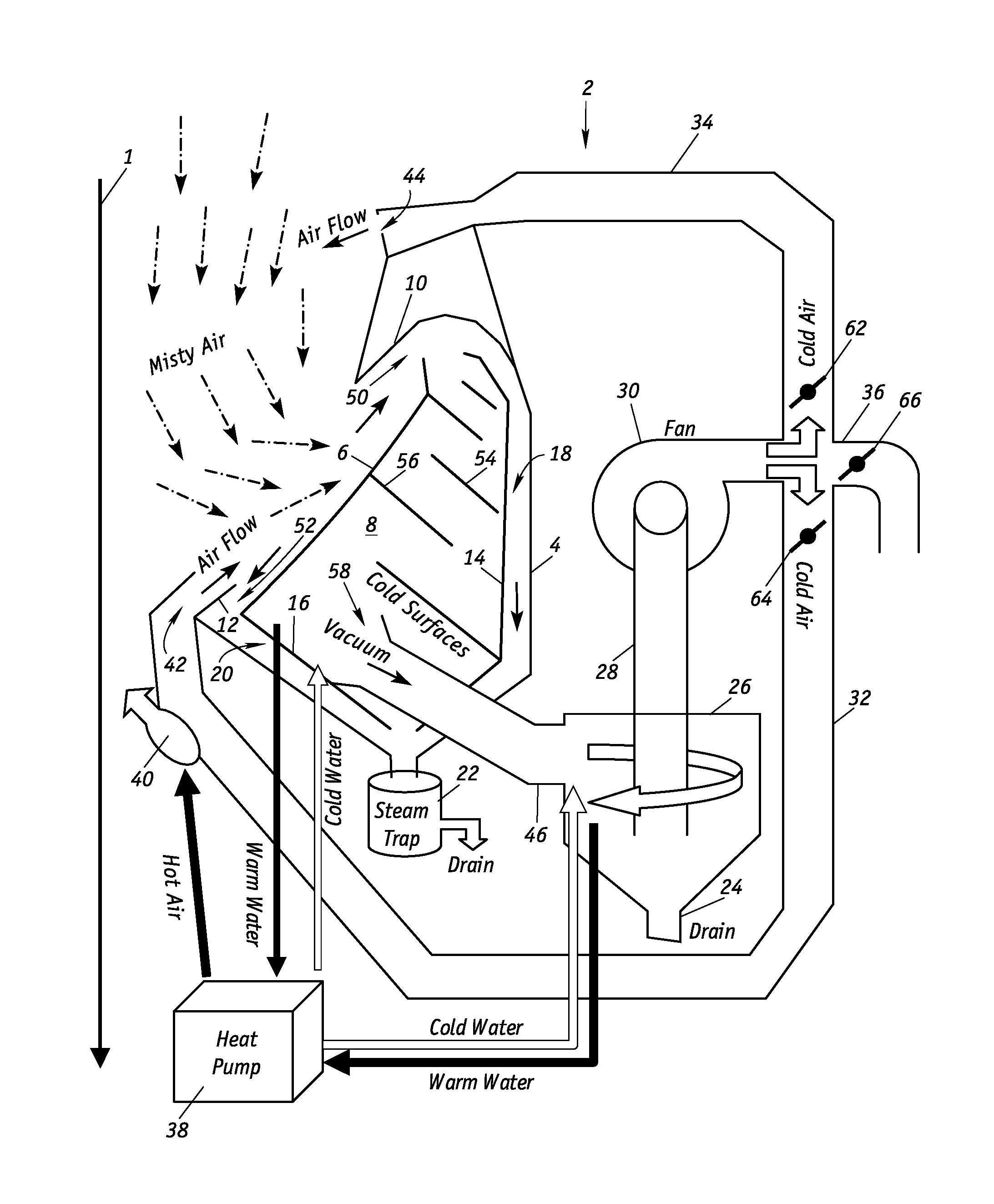
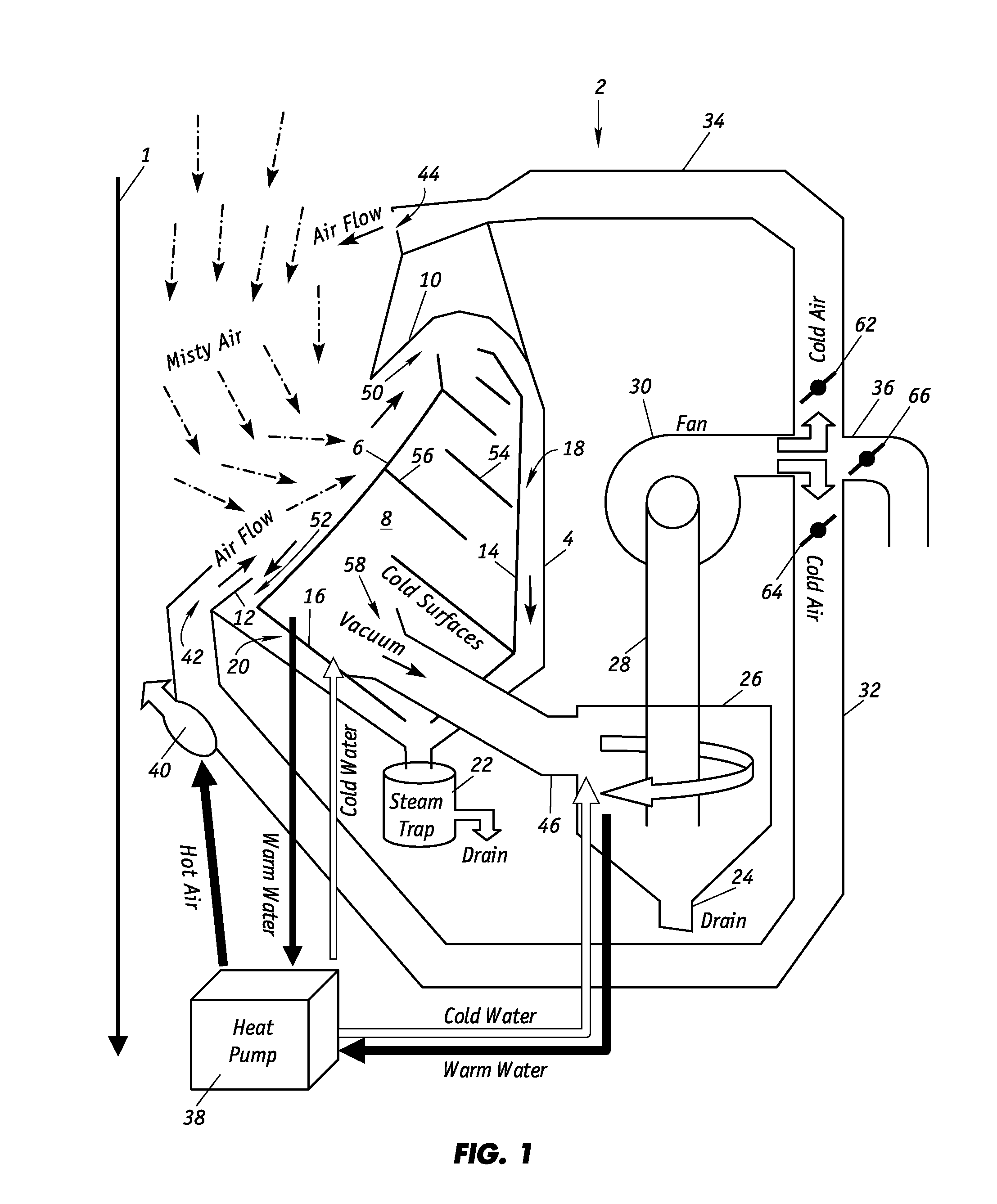
[0010]The inventive apparatus is particularly suited for used in a papermaking machine to capture excess steam and water droplets in the form of misty air that is generated in rewet and steam shower applications. In a preferred embodiment, the configuration of the housing facing the misty air takes advantage of the natural motion of the cloud of misty air that develops by defining an entry point into the chamber that initially accelerates the velocity of the misty air. Moreover, the internal structures within the chamber near the entry point are preferably designed with an abrupt turn away from the direction of flow so that centrifugal forces facilitate the separation of free droplets from the steam of the misty air. The free droplets are readily collected and drained away from the papermaking machine.

Problems solved by technology

Unfortunately, in both rewet and steam shower processes, water tends to accumulate in the vicinity adjacent the points of application.
Large water droplets develop on surrounding structures that can result in the formation of rust and related problems.
Conventional vacuum boxes, which are not energy efficient, demonstrate only limited success in removing the excess steam and moisture; as a result, the excess water is detrimental to the production of high quality paper and the operations of the machinery.

Method used


Image

  • Proactive steam and mist removal system
  • Proactive steam and mist removal system
  • Proactive steam and mist removal system

Examples


Embodiment Construction

[0024]The steam and mist removal device of the present invention can be employed in any environment such as an industrial setting where excess steam and / or mist are continuously generated. The device is particularly suited for employment in an enclosed area where steam and water droplets do not readily dissipate into the atmosphere.

[0025]As illustrated in FIG. 1, the steam and mist removal device 2 includes a housing 4 that defines a chamber 8 with an opening that is partially shielded by front panel 6. Upper flange 10 of housing 4 and the upper end of panel 6 define an upper entrance 50 into chamber 8. Lower flange 12 of housing 4 and the lower end of panel 6 define a lower entrance 52. A rear inner panel 14 having a surface that preferably matches that of housing 4 forms a rear channel 18 where condensate collects. Similarly, a lower front inner panel 16 having a surface that preferably matches that of housing 4 forms a front channel 20 where condensate collects. Channels 18, 20 c...


PUM

PropertyMeasurementUnit
vacuumaaaaaaaaaa
gravityaaaaaaaaaa
pressureaaaaaaaaaa

Abstract

A proactive steam and mist removal apparatus is employed along a point of application of a rewet or steam shower system to remove excess steam and water droplets to prevent damage to machinery and products. The apparatus includes an internal chamber equipped with cooled baffles that promote condensation and a condensate collection mechanism. A vacuum source draws a stream of ambient steam and water droplets from the environment along a path into the chamber and a projected gas stream directs the stream into the chamber wherein at least a portion of the ambient steam condenses into condensate. The remaining portion of ambient steam is separated into water and cold air that is recycled as the projected gas. Steam and moisture that escape capture into the internal chamber are heated by a hot air blower that raises their relatively humidity so that the dried air dissipates harmlessly into the atmosphere.

Description

FIELD OF THE INVENTION[0001]The present invention generally relates to techniques for removing excess steam and moisture and particularly to devices for removing water vapor and mist that are generated by steaming and rewet systems employed in papermaking machines.BACKGROUND OF THE INVENTION[0002]In the manufacture of paper on continuous papermaking machines, a web of paper is formed from an aqueous suspension of fibers (stock) on a traveling mesh papermaking fabric as water drains by gravity and suction through the fabric. The web is then transferred to the pressing section where more water is removed by pressure and vacuum. The web next enters the dryer section where steam heated dryers and hot air completes the drying process. The papermaking machine is, in essence, a water removal, system.[0003]Conventional papermaking machinery includes equipment to set the sheet properties of the paper as it is being manufactured. One of the more basic operations on a papermaking machine is co...

Claims


Application Information

Patent Timeline
Patent Type & Authority Patents(United States)
IPC IPC(8): B01D45/08
CPCB01D45/08B01D45/12B01D53/265B01D2258/02
Inventor MAKINEN, TUOMO TAPIO
Owner HONEYWELL INT INC
Learn More