Vibrating hand-held power tool

a hand-held power tool and vibration technology, applied in the direction of portable power-driven tools, portable percussive tools, machine supports, etc., can solve the problem of ineffective windings of this abutting portion

Inactive Publication Date: 2013-08-20
HILTI AG
View PDF8 Cites 2 Cited by
  • Summary
  • Abstract
  • Description
  • Claims
  • Application Information

AI Technical Summary

Benefits of technology

[0011]The compressive preload of a portion of the spring wire coil spring and of the outer thread of the threaded plug provides, on opposite sides of a linear flat middle region, in which all of the winding in that region lie free, edge regions, respectively, with steeper characteristics and in which a portion of the windings abuts the outer thread and, therefore, the windings of this abutting portion are not any more effective. In the low-loaded region, in which a portion of the windings is compressively preloaded in the preload region, the spring rate characteristic is linearly steep because only the free-lying windings are operative. In the high-loaded region, in which an increased portion of windings within the preload region abuts portions of the outer thread, the spring rate characteristic progressively increases because an increasingly smaller number of winding is elastically effective. In the highest-loaded region, in which the windings within the preload region, spring-side, completely abut the outer thread, the spring rate characteristic is linearly steep, as only the free-lying windings are elastically effective.
[0012]In order to achieve the compressive preload, the preload region, which is inwardly limited by the thread ends of the outer thread, should be shorter than the outer limited portion of the unloaded coil spring with the same number of windings. Thus, the coil spring outwardly abuts the inside contact surfaces of the thread ends, whereby the coil spring becomes compressively preloaded until in the middle region, it is adequately shortened and, thus, becomes disengaged from one contact surface.

Problems solved by technology

The compressive preload of a portion of the spring wire coil spring and of the outer thread of the threaded plug provides, on opposite sides of a linear flat middle region, in which all of the winding in that region lie free, edge regions, respectively, with steeper characteristics and in which a portion of the windings abuts the outer thread and, therefore, the windings of this abutting portion are not any more effective.

Method used


Image

  • Vibrating hand-held power tool
  • Vibrating hand-held power tool
  • Vibrating hand-held power tool

Examples


Embodiment Construction

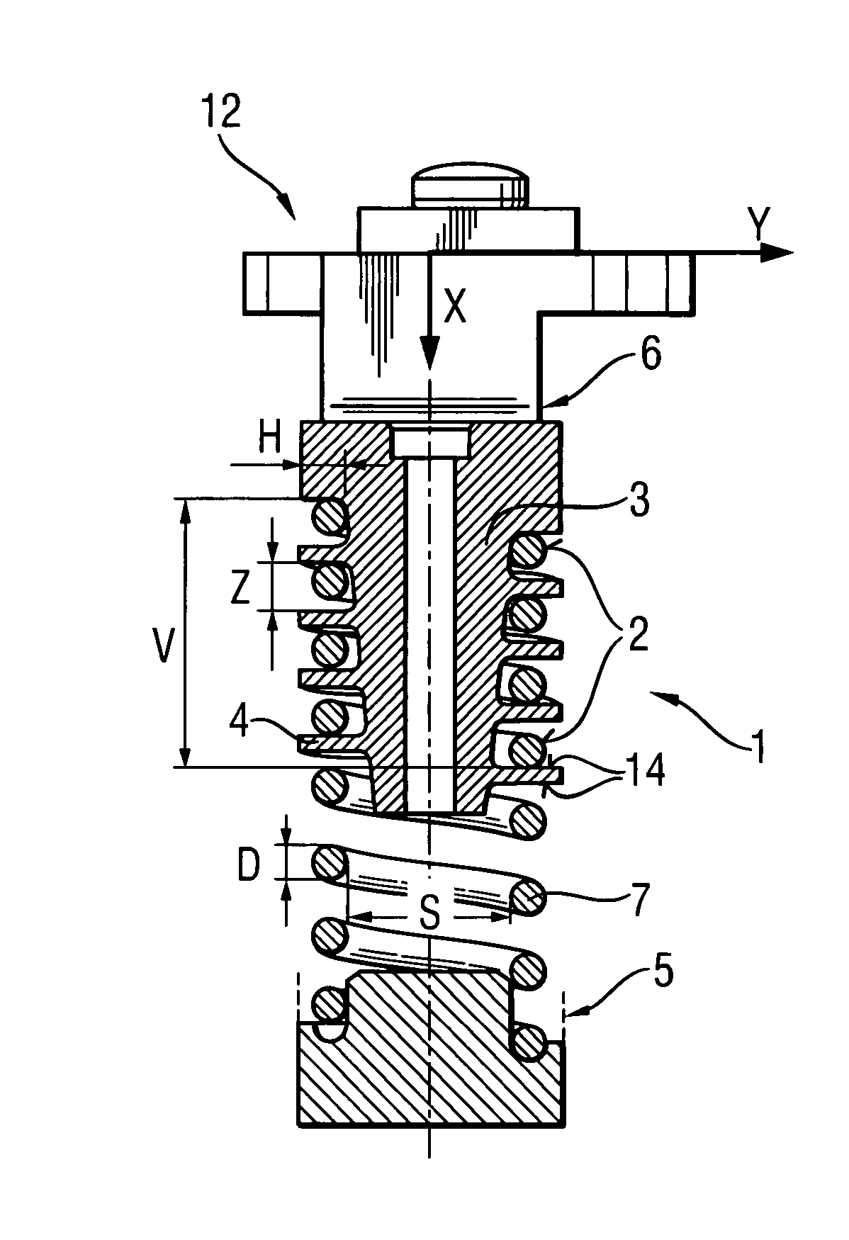
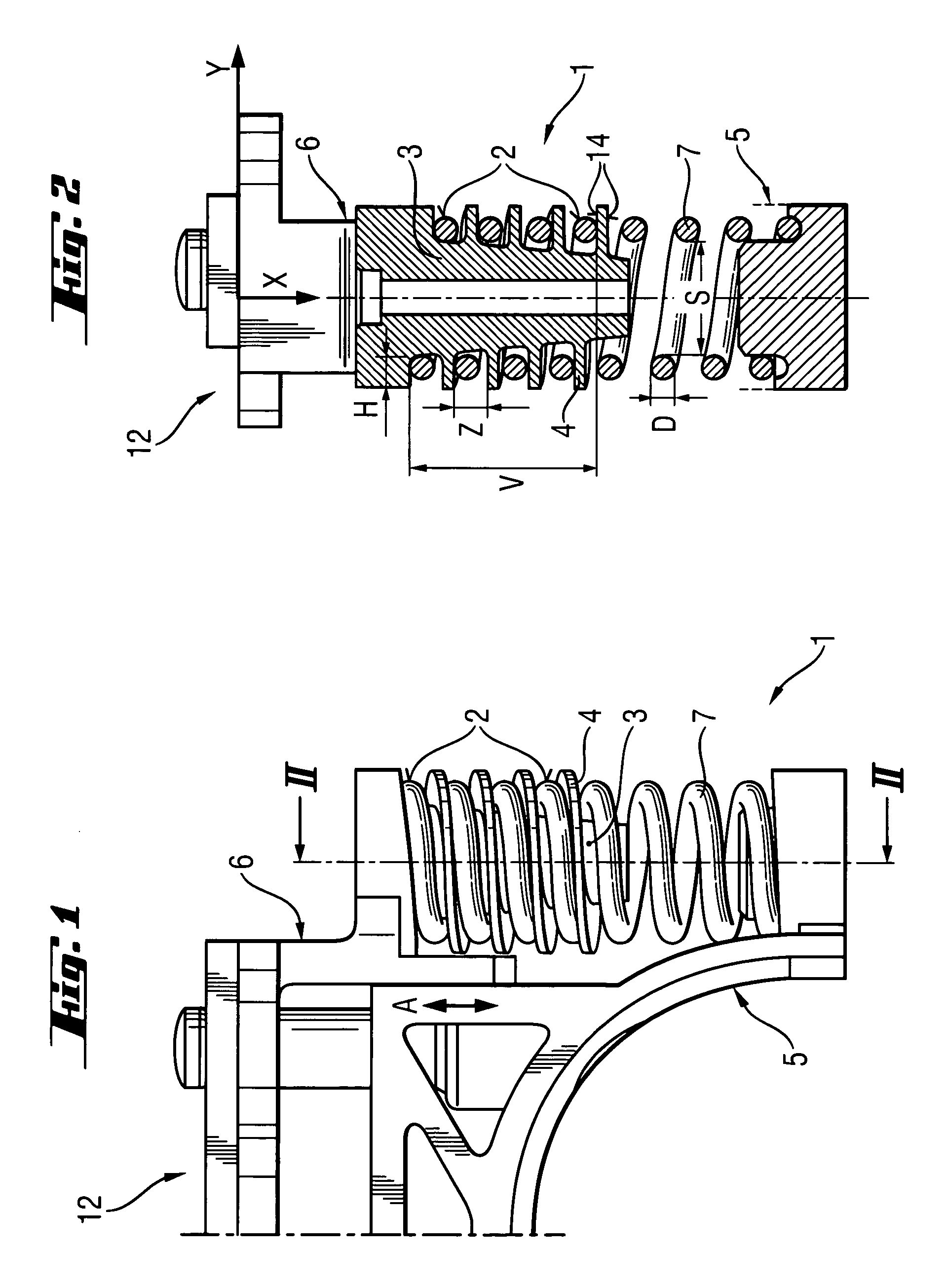
[0024]A hand-held power tool 12, a detail of which is shown in FIG. 1, is formed as a chisel hammer and includes an antivibration element 1 arranged between a vibrating sub-assembly 5 that vibrates along a vibration axis A and a vibration-decoupled handle sub-assembly 6. The antivibration element 1 has a coil 7 which is formed of a spring wire, is oriented along the vibration axis A, and has a plurality of windings 2 that are wound at one end of the coil 7 on a threaded plug 3 provided with an outer thread 4. The antivibration element 1 has a cylindrical shape and the same pitch of the windings 2.

[0025]As shown in FIG. 2, in a case of loading of the antivibration element 1 in which it is not subjected to a compression load, different winding 2, contact axially, both spring-side and plug-side in a preload region V, contact surfaces 14 of the outer thread 4. The width Z between the flights of the outer thread 4 is greater than a diameter D of the spring wire coil is formed off. Differ...


PUM


Abstract

A hand-held power tool includes an antivibration element (1) for vibrationally decoupling a handle sub-assembly (6) from another sub-assembly (5) that vibrates along a vibration axis (A), and having a coil spring (7) oriented along the vibration axis (A), and a threaded plug (3) provided with an outer thread (4) longitudinally extending therealong, with the coil spring (7) having a plurality of windings (2) extending along a preload region (V) and screwed on the outer thread (4) under an axial compressive preload, and with the outer thread (4) having a between-flight width (Z) greater than a diameter (D) of the spring wire of which the coil spring (7) is formed.

Description

BACKGROUND OF THE INVENTION[0001]1. Field of the Invention[0002]The present invention relates to a hand-held power tool and, in particular hammer drill or chisel hammer, including a sub-assembly that vibrates along a vibration axis, a handle sub-assembly, and an antivibration element for vibrationally decoupling the handle sub-assembly from the first-mentioned sub-assembly.[0003]2. Description of the Prior Art[0004]Usually, in vibrating hand-held power tool, the handle is decoupled from vibration-transmitting parts to a most possible extent, with the handle being connected with a vibrating part or sub-assembly by an antivibration element. The antivibration element can have both spring and damping characteristics.[0005]At infinitesimal stresses, each spring rate characteristic is linear, which is typical for low-loaded helical springs. At large stresses, dependent on material properties, the spring rate characteristic is increasingly non-linear, in particular, when elastomers are use...

Claims


Application Information

Patent Timeline
Patent Type & Authority Patents(United States)
IPC IPC(8): F16F1/06
CPCB25D17/043B25F5/006B25D2250/361B25D2250/371
Inventor MOESSNANG, FRANZ
Owner HILTI AG
Why Eureka
Try Eureka