

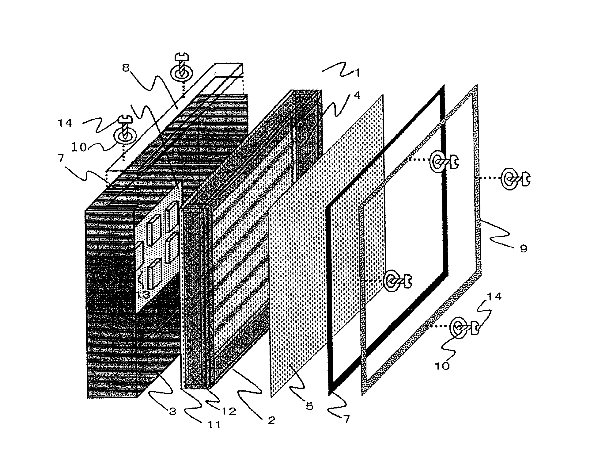
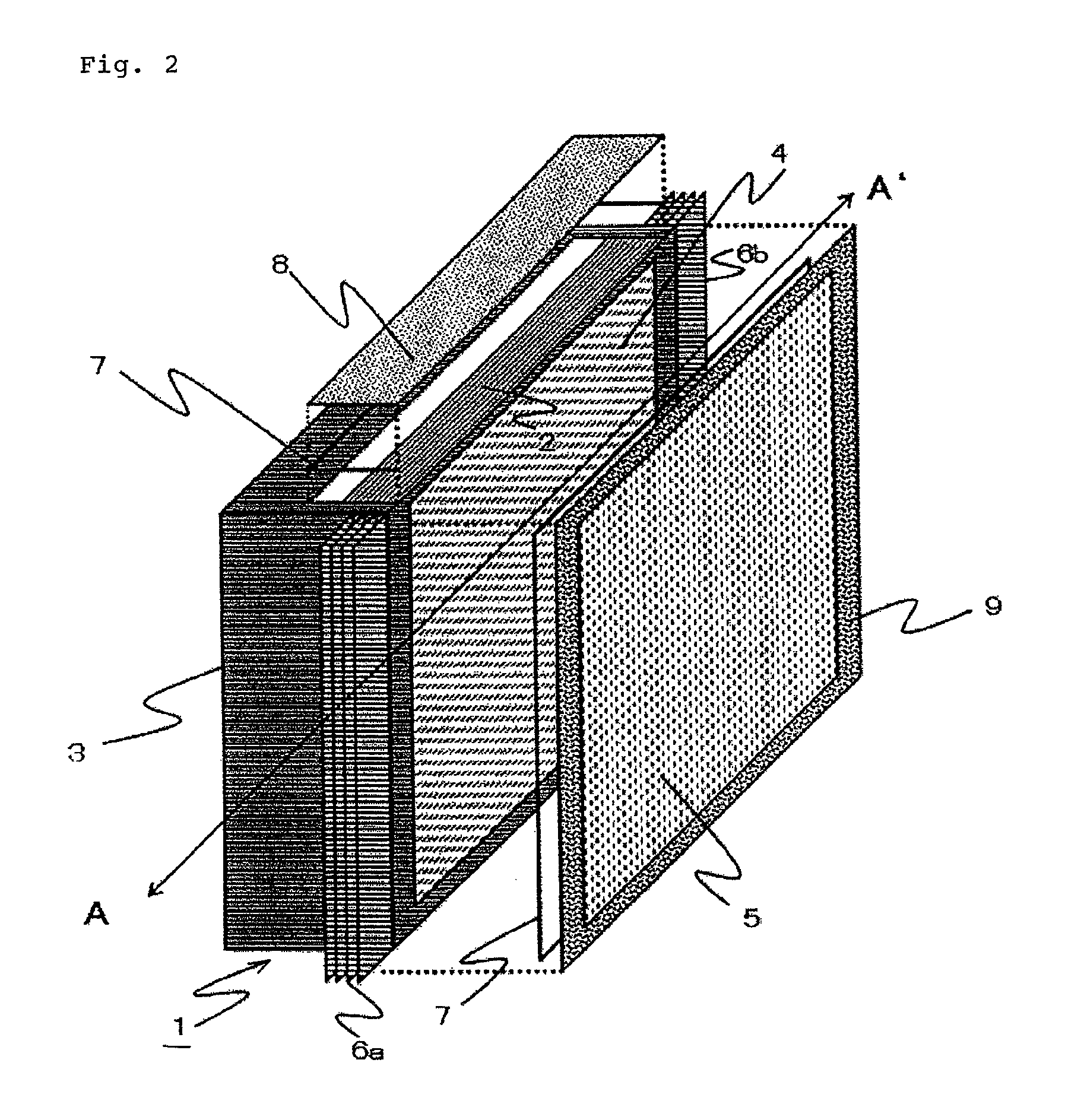
Dust and dirt resistant liquid crystal display device
a liquid crystal display and dust-resistant technology, applied in the field of large-scale liquid crystal display devices, can solve the problems of poor thermal conductivity of the transparent non-reflective plate covering the surface affecting the provision of uniform image quality, and affecting the reliability of the liquid crystal panel, etc., to achieve tight closing
- Summary
- Abstract
- Description
- Claims
- Application Information
AI Technical Summary
Benefits of technology
Problems solved by technology
Method used
Image

Examples
second embodiment
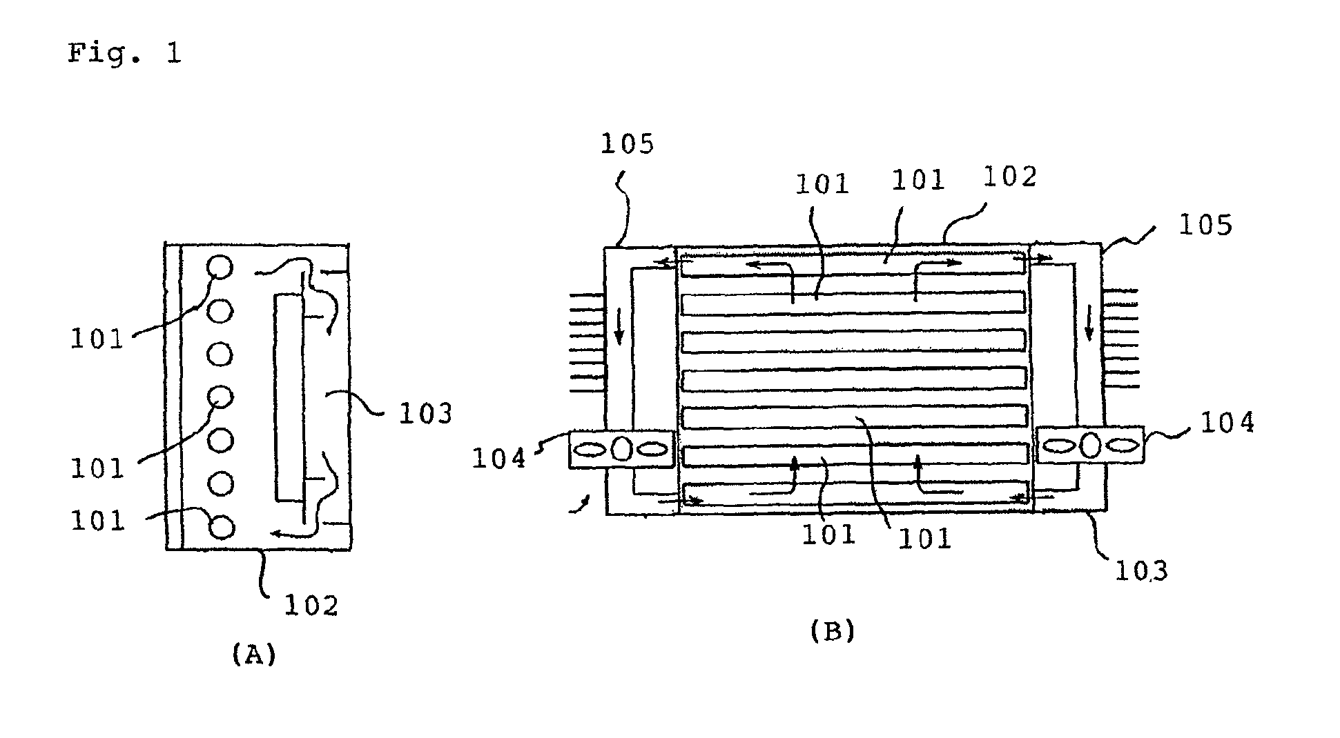
[0132]A second embodiment of the present invention will be described with reference to FIG. 10. In addition, FIG. 10 shows enlarged area B shown in FIG. 8.
[0133]The configuration of this embodiment is almost the same as the above-mentioned configuration in FIG. 8. However, only one large difference is in that the side surface of fluorescent lamp socket 25a does not come into with the side surface of chassis box 11. More specifically, there is an air layer between the side surface of fluorescent lamp socket 25a and the side surface of chassis box 11.
[0134]In this configuration, in FIG. 10, heat dissipation paths for fluorescent lamp 19 as a heat source, and for inverter circuit board 26a as a heat source, are expressed by a thermal network.
[0135]First, the heat generated from a plurality of fluorescent lamps 19 including other fluorescent lamps 19, not shown, is dissipated into the air around device 1 from three heat dissipation paths 1) to 3) below.
1) A heat dissipation path to the ...
PUM
| Property | Measurement | Unit |
|---|---|---|
| thickness | aaaaa | aaaaa |
| size | aaaaa | aaaaa |
| height | aaaaa | aaaaa |
Abstract
Description
Claims
Application Information