
Shrouded sensor clip assembly and blood chamber for an optical blood monitoring system

a blood monitoring system and sensor clip technology, applied in the field of optical blood monitoring systems, can solve the problems of serious inaccuracy in the measurement of hematocrit and/or oxygen saturation, the addition of medical grade polycarbonate material to manufacture the raised rim, and the stepping of the rim, so as to minimize the possibility of light piping

Active Publication Date: 2013-08-27
FRESENIUS MEDICAL CARE HLDG INC
View PDF45 Cites 17 Cited by
  • Summary
  • Abstract
  • Description
  • Claims
  • Application Information

AI Technical Summary

Benefits of technology

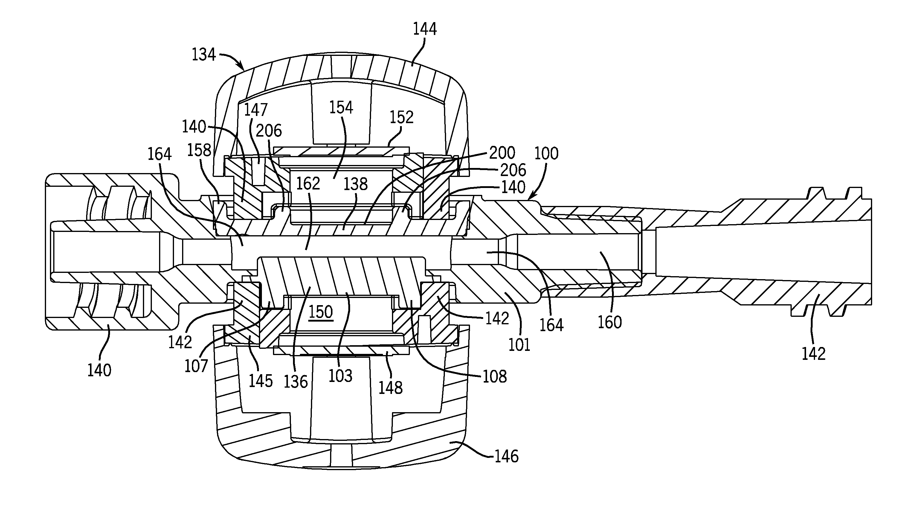
The invention is about an optical blood monitoring system that uses a sensor clip assembly and a blood chamber designed to physically block ambient light from the photodetectors on the sensor clip assembly. The sensor clip assembly has a clippable connection to the blood chamber and includes an emitter subassembly with an emitter clip and a detector subassembly with a detector clip. The emitter subassembly has a shroud to prevent ambient light from entering the blood chamber and the detector subassembly has a similar shoud. The heads on the sensor clip and detector subassembly have a shroud to enclose the LED emitters and photodetectors, respectively. The purpose is to distribute light energy across the blood in the lens areas of the blood chamber to avoid hot spots of concentrated light from the emitters for consistency in calibrations. The emitter and detector shrouds effectively surround the viewing lenses on both sides of the blood chamber and block ambient light. The design reduces the influx of ambient light and enables the use of less molded material in the blood chamber. The blood chamber has anti-rotation tabs to fix the position of the sensor clip assembly and prevent rotation relative to the blood chamber.

Problems solved by technology

While the double-D configuration has proven to work well, one drawback of the design is the additional amount of medical grade polycarbonate material that is required to manufacture the raised, stepped rims.
If not addressed properly, stray ambient light and light piping through the blood chamber can cause serious inaccuracies in the measured hematocrit and / or oxygen saturation levels.

Method used


Image

  • Shrouded sensor clip assembly and blood chamber for an optical blood monitoring system
  • Shrouded sensor clip assembly and blood chamber for an optical blood monitoring system
  • Shrouded sensor clip assembly and blood chamber for an optical blood monitoring system

Examples


Embodiment Construction

[0024]FIG. 6 is a perspective view of one side of a blood chamber constructed in accordance with an embodiment of the invention.

[0025]FIG. 7 is a perspective view of the other side of the blood chamber shown in FIG. 6.

[0026]FIG. 8 is a front elevation view of the blood chamber shown in FIG. 6.

[0027]FIG. 9 is a is a longitudinal sectional view taken along line 9-9 in FIG. 6.

[0028]FIG. 10 is a perspective view showing a sensor clip assembly constructed in accordance with an embodiment of the invention.

[0029]FIG. 11 is a perspective view showing the sensor clip assembly of FIG. 10 engaged with the blood chamber of FIG. 6.

[0030]FIG. 12 is a longitudinal sectional view of taken along line 12-12 in FIG. 11.

DETAILED DESCRIPTION

Prior Art

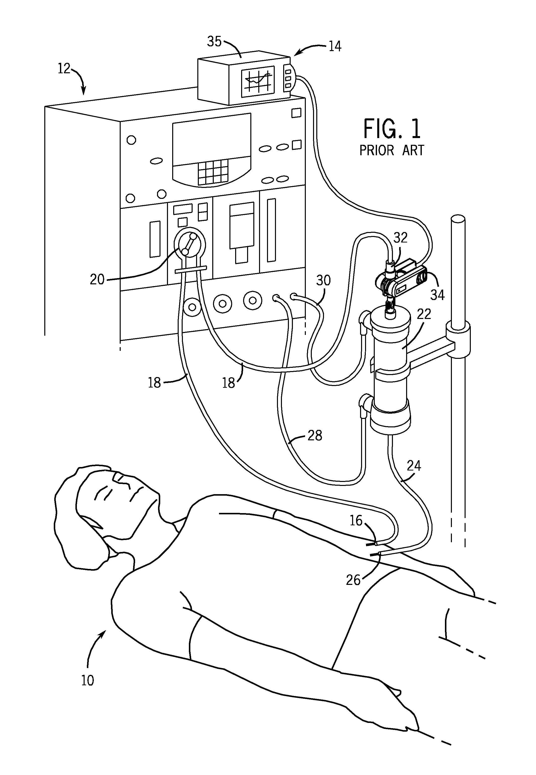
[0031]FIG. 1 illustrates a patient 10 undergoing hemodialysis treatment with a conventional hemodialysis system 12, and also illustrates a non-invasive, optical blood monitor 14. A typical hemodialysis clinic will have several hemodialysis systems 12 for tre...


PUM

PropertyMeasurementUnit
wavelengthsaaaaaaaaaa

Abstract

An optical blood monitoring system includes a sensor clip assembly and a blood chamber. The blood chamber has an internal flow cavity for extracorporeal blood flow and viewing lenses to enable the sensor clip assembly to monitor the blood when it is mounted on the blood chamber. The sensor clip assembly includes an annular shroud surrounding the LED emitters and another annular shroud surrounding the photodetectors, both for the purpose of blocking ambient light and limiting light piping. The blood chamber includes separate, distinct shroud mating surfaces to engage the shrouds on the sensor clip assembly.

Description

FIELD OF THE INVENTION[0001]The invention relates to optical blood monitoring systems used to monitor extracorporeal patient blood flow and take real-time measurement of hematocrit, oxygen saturation levels and / or other blood constituents. The invention is particularly directed to improving the physical interface between the sensor clip assembly and the mating, single-use blood chamber.BACKGROUND[0002]The type of blood monitoring systems to which the invention pertains has been widely used to monitor a patient's hematocrit and oxygen saturation levels during conventional hemodialysis treatments. Patients with kidney failure or partial kidney failure typically undergo hemodialysis treatment in order to remove toxins and excess fluids from their blood. To do this, blood is taken from a patient through an intake needle or catheter which draws blood from an artery or vein located in a specifically accepted access location (for example, a shunt surgically placed in an arm, thigh, subclav...

Claims


Application Information

Patent Timeline
Patent Type & Authority Patents(United States)
IPC IPC(8): A61M37/00G01N33/48
CPCA61B5/14535A61B5/14557A61M1/367A61B5/1455A61B2562/185A61M39/10A61M2205/3306A61M2205/3313A61M2230/205A61M2230/207
Inventor BARRETT, LOUIS L.LAW, PERRY N.
Owner FRESENIUS MEDICAL CARE HLDG INC
Learn More