System and method for balancing charge within a battery pack

a technology of charge balancing and battery pack, applied in adaptive control, process and machine control, instruments, etc., can solve the problems of increased chance of battery pack failure, waste of extra charge through resistors, and failure of battery packs, so as to increase the initial charge rate of capacitors, increase the voltage potential, and speed up the speed of charge balancing

Active Publication Date: 2013-08-27
MOTIV POWER SYST
View PDF22 Cites 28 Cited by
  • Summary
  • Abstract
  • Description
  • Claims
  • Application Information

AI Technical Summary

Benefits of technology

[0003]Battery packs are increasingly produced with many battery cells that are electrically connected to each other within the battery pack. While of the same specification, each battery cell within battery packs may operate differently; in particular, each battery cell may hold charge differently. This may be a result of manufacturing differences between cells, age difference between cells, or any other suitable source of differences. A battery pack with cells that are at different charge levels may have a decreased battery pack lifetime. For example, a cell within a battery pack that has a higher charge level may operate at a temperature that is higher than an optimal operating temperature for the cell. This may cause that particular cell within the battery pack to catastrophically fail, which may then lead to neighboring cells catastrophically failing and / or may lead to failure of the battery pack. This is especially true when the rate of energy transfer to and from the battery pack is substantially high (for example, during high power charge or discharge situations). If there is a charge imbalance within the battery pack, a high rate of energy transfer to and from the cells may cause the charge imbalance to be further amplified in a substantially short period of time, which may lead to increased chance of failure of the battery pack.
[0004]Currently available systems and methods for balancing charge include dissipating extra charge from imbalanced cells, which results in the waste of the extra charge through the resistors. Other available systems balance charge by transferring charge from one cell to another. Available charge balancing circuits are complicated and expensive to manufacture (e.g., charge balancing circuits that require sensors and capacitors at each cell within the battery pack). Other available charge balancing circuits may be too slow in balancing charge within the battery pack (e.g., charge balancing circuits that transfer charge between imbalanced cells by utilizing the difference in voltage potential between the imbalanced cells, which may be very slow if difference is relatively small, and / or may only allow for charge transfer between certain cells within the battery pack). As mentioned above, charge imbalances may be amplified in a substantially short period of time in scenarios where the rate of energy transfer to and from the battery pack is high. If the charge balancing circuit is not fast enough to balance charge to prevent the amplification of charge imbalance, battery pack failure may not be prevented.
[0008]In the system of the preferred embodiments, the processor may select a combination of donor cells and receiver cells in a first mode where the number of donor cells and receiver cells are equal and in a second mode where the number of donor cells is greater than the number of receiver cells. In usage scenarios that require a faster speed of charge balancing, the processor may select a combination of donor cells and receiver cells according to the second mode. For example, a substantially large number of donor cells that are connected in series (for example, if the number of the plurality of cells is N, then the number of donor cells may be up to N cells) to charge the capacitor and a substantially small number of receiver cells that are connected in series (for example, one) to discharge the capacitor. Thus, the voltage potential difference between the donor cells connected in series and the capacitor is significantly high, increasing the initial charge rate of the capacitor. The charged capacitor is then at a substantially higher voltage potential than the receiver cell, increasing the initial discharge rate of the capacitor and substantially increasing the charge transfer rate between the cells within the battery pack. Additionally, the increased combined voltage potential of the donor cells allows for an increased amount of charge to be transferred to the receiver cells in a fixed-time charge and discharge cycle of the capacitor, increasing the speed of charge balancing within the battery pack over existing charge balancing circuits by orders of magnitude. The processor may alternatively select any other suitable combination of donor cells and receiver cells to increase the charge transfer rate between cells.
[0009]With increased rate of charge transfer between the donor cells, the capacitor, and the receiver cells, there may be a decrease in charge transfer efficiency between cells. For example, with the increased charge current, energy may be lost through heat dissipated through the circuit. Thus, in usage scenarios that do not require a high rate of charge transfer between cells, the processor may select a combination of donor cells and receiver cells according to the first mode. For example, one donor cell and one receiver cell. This will result in a lower initial charge / discharge rate of the capacitor, which may allow for an increase in charge transfer efficiency between cells. Alternatively, the processor may select a combination of donor cells and receiver cells according to the second mode, but with a smaller difference between the number of donor and number of receiver cells. The processor may alternatively select any other suitable combination of donor cells and receiver cells to increase the charge transfer efficiency between cells.
[0010]The charge balancing system of the preferred embodiments allows for increased flexibility in charge balancing. By allowing selection of combinations of donor cells and receiver cells of a first and a second mode, any number of and any of the plurality of cells may function as donor cells and receiver cells interchangeably and the rate of charge transfer and the efficiency of charge transfer between cells may be optimized for different usage scenarios, which may result in a more balanced and healthy battery pack.BRIEF DESCRIPTION OF THE FIGURES

Problems solved by technology

This may cause that particular cell within the battery pack to catastrophically fail, which may then lead to neighboring cells catastrophically failing and / or may lead to failure of the battery pack.
If there is a charge imbalance within the battery pack, a high rate of energy transfer to and from the cells may cause the charge imbalance to be further amplified in a substantially short period of time, which may lead to increased chance of failure of the battery pack.
Currently available systems and methods for balancing charge include dissipating extra charge from imbalanced cells, which results in the waste of the extra charge through the resistors.
Available charge balancing circuits are complicated and expensive to manufacture (e.g., charge balancing circuits that require sensors and capacitors at each cell within the battery pack).
Other available charge balancing circuits may be too slow in balancing charge within the battery pack (e.g., charge balancing circuits that transfer charge between imbalanced cells by utilizing the difference in voltage potential between the imbalanced cells, which may be very slow if difference is relatively small, and / or may only allow for charge transfer between certain cells within the battery pack).
As mentioned above, charge imbalances may be amplified in a substantially short period of time in scenarios where the rate of energy transfer to and from the battery pack is high.
If the charge balancing circuit is not fast enough to balance charge to prevent the amplification of charge imbalance, battery pack failure may not be prevented.
In most cases, especially for cells whose state of charge is neither very high nor very low, the voltage potential difference between two imbalanced cells may not be very large, further slowing the charge transfer rate.
The resulting charge transfer rate in such charge balancing circuits may not be fast enough for certain usage scenarios.
For example, an increased rate of energy transfer into or out of the battery pack during high power charging or discharging may amplify existing charge imbalances in a very short period of time, which may lead to catastrophic failure of the battery pack.
A charge balancing circuit that is slow (for example, capable of transferring only enough charge away from the imbalanced cell and into other cells in the battery pack to decrease the voltage of the imbalanced cell by 0.1 volts per hour) will not be fast enough to prevent the imbalanced cell from becoming more imbalanced and possibly failing.
Thus, the voltage potential difference between the donor cells connected in series and the capacitor is significantly high, increasing the initial charge rate of the capacitor.
With increased rate of charge transfer between the donor cells, the capacitor, and the receiver cells, there may be a decrease in charge transfer efficiency between cells.
For example, with the increased charge current, energy may be lost through heat dissipated through the circuit.

Method used


Image

  • System and method for balancing charge within a battery pack
  • System and method for balancing charge within a battery pack
  • System and method for balancing charge within a battery pack

Examples


Embodiment Construction

[0018]The following description of the preferred embodiments of the invention is not intended to limit the invention to these preferred embodiments, but rather to enable any person skilled in the art to make and use this invention.

1. System for Balancing Charge

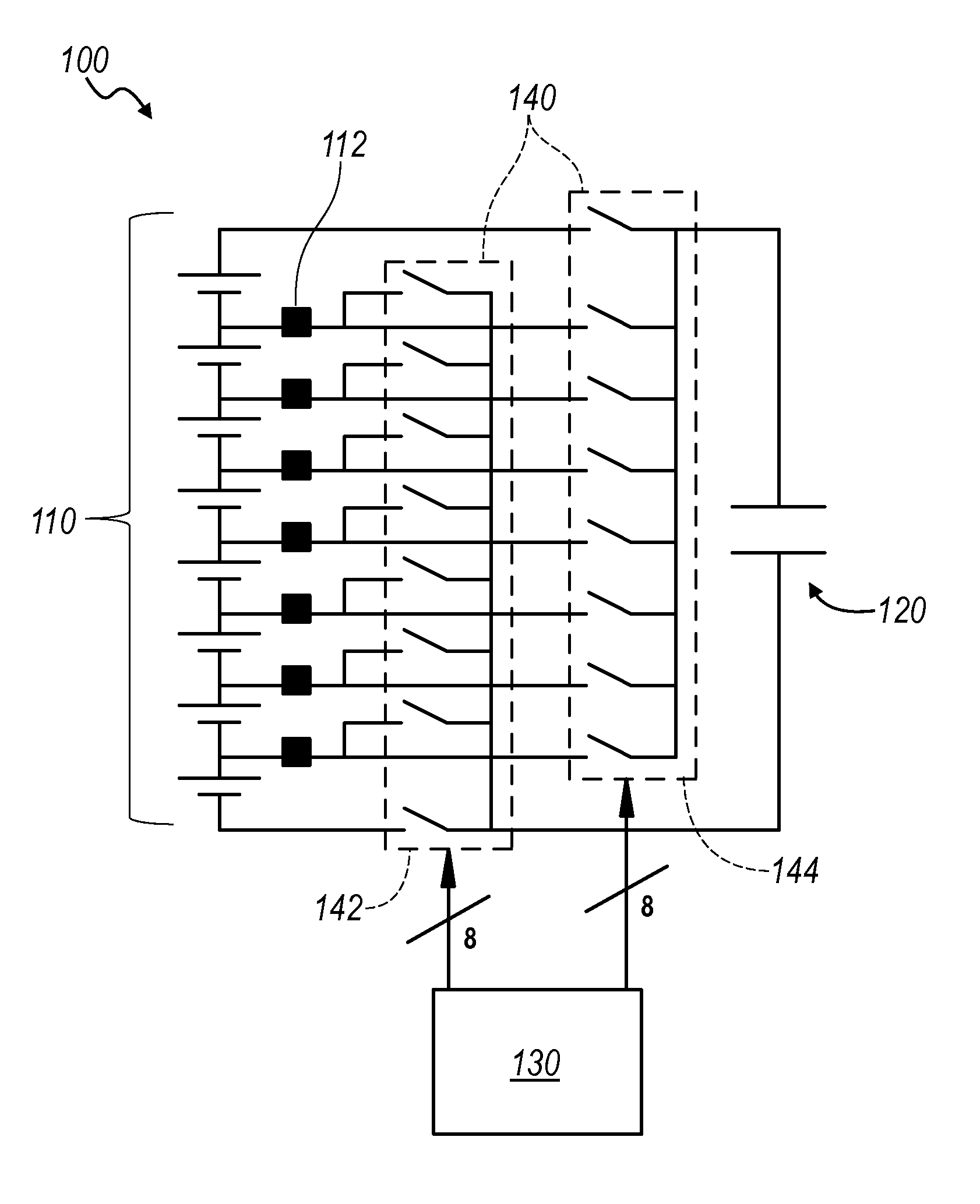
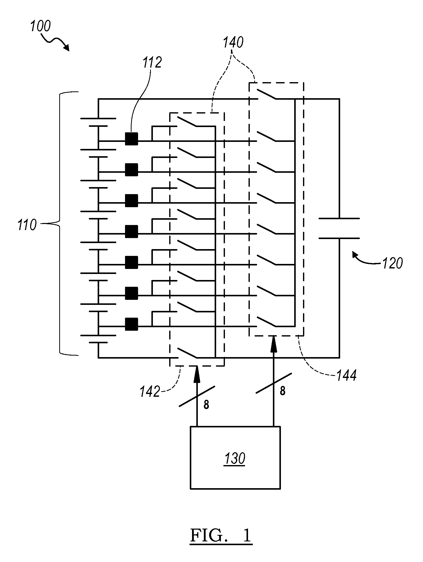
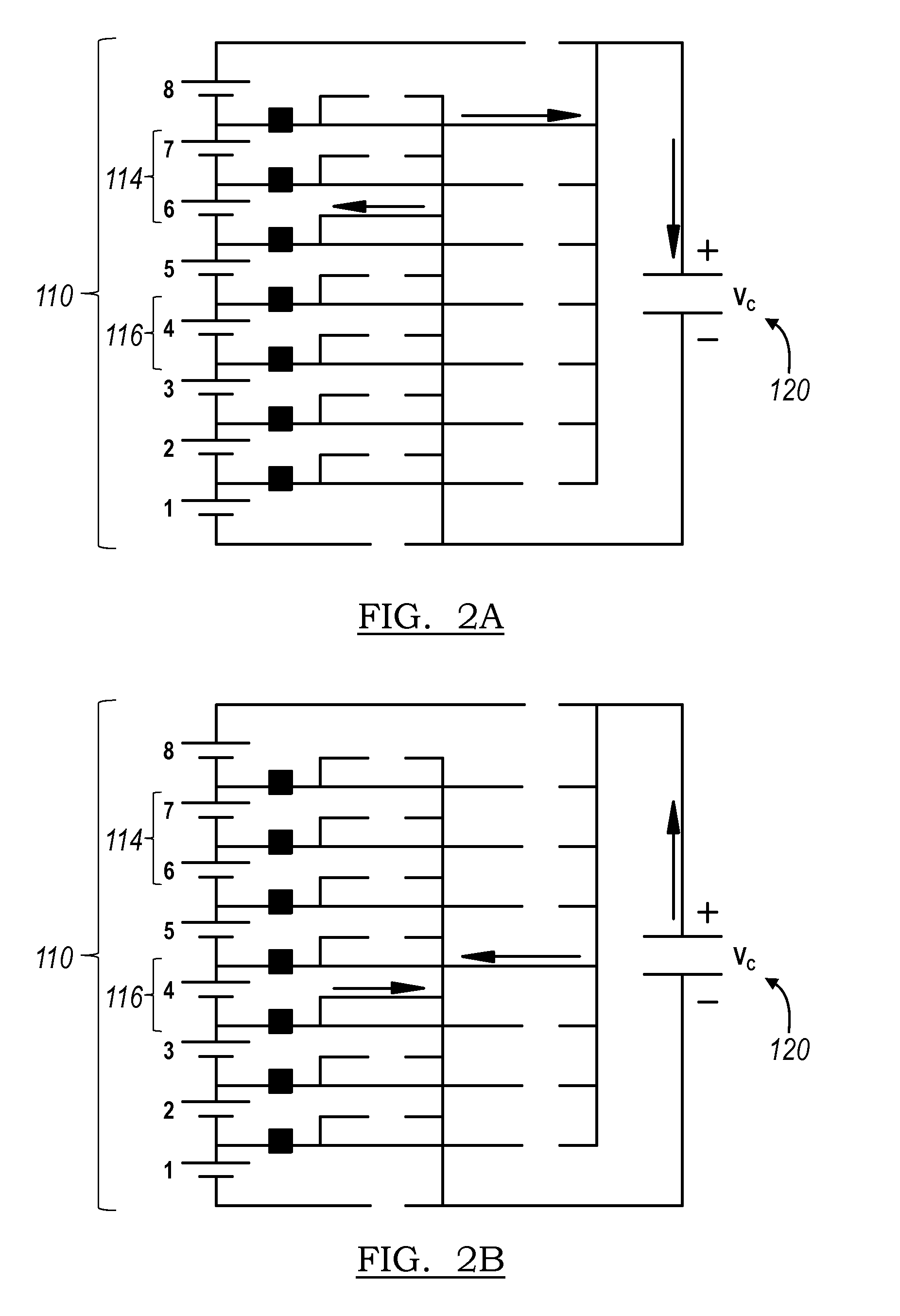
[0019]As shown in FIGS. 1 and 2, the system 100 of the preferred embodiments for balancing charge within a battery pack with a plurality of cells 110 connected in series includes a capacitor 120, a processor 130 that is configured to select a combination of donor cells 114 and receiver cells 116 from the plurality of cells 110 in one of following two modes: a first mode where the number of donor cells is equal to the number of receiver cells and a second mode where the number of donor cells is greater than the number of receiver cells, and a plurality of switches 140 that electrically couple the capacitor 120 to the donor cells 114 to charge the capacitor 120 and electrically couple the capacitor to the receiver cells 116 to d...


PUM


Abstract

A system for balancing charge within a battery pack with a plurality of cells connected in series, including a capacitor; a processor configured to select a combination of donor cells and receiver cells from the plurality of cells in one of the following two modes: (1) a first mode where the number of donor cells is equal to the number of receiver cells, and (2) a second mode where the number of donor cells is greater than the number of receiver cells; and a plurality of switches that electrically connect the capacitor to the donor cells to charge the capacitor, and that electrically connected the capacitor to the receiver cells to discharge the capacitor. The transfer of charge between cells in the plurality of cells through the capacitor balances the charge within the battery pack.

Description

CROSS-REFERENCE TO RELATED APPLICATIONS[0001]This application claims the benefit of U.S. Provisional Application No. 61 / 210,847 filed on 23 Mar. 2009 and entitled “Multiple Cell Charge Pump for Active Battery Management”, which is incorporated in its entirety by this reference.TECHNICAL FIELD[0002]This invention relates generally to the portable electric power field, and more specifically to a new and useful charge balancing system and method in the battery pack management field.BACKGROUND AND SUMMARY[0003]Battery packs are increasingly produced with many battery cells that are electrically connected to each other within the battery pack. While of the same specification, each battery cell within battery packs may operate differently; in particular, each battery cell may hold charge differently. This may be a result of manufacturing differences between cells, age difference between cells, or any other suitable source of differences. A battery pack with cells that are at different cha...

Claims


Application Information

Patent Timeline
Patent Type & Authority Patents(United States)
IPC IPC(8): H02J7/00
CPCH02J7/345H02J7/0019Y02T10/7055G05B13/00Y02T10/70
Inventor CASTELAZ, JIMRILEY, JESSICAPARIKH, VISHALDIAMOND, STEVENCHANG, SAMUEL
Owner MOTIV POWER SYST
Why Eureka
Try Eureka