[0003]Battery packs are increasingly produced with many battery cells that are electrically connected to each other within the battery pack. While of the same specification, each
battery cell within battery packs may operate differently; in particular, each battery cell may hold charge differently. This may be a result of manufacturing differences between cells, age difference between cells, or any other suitable source of differences. A battery pack with cells that are at different charge levels may have a decreased battery pack lifetime. For example, a cell within a battery pack that has a higher charge level may operate at a temperature that is higher than an optimal
operating temperature for the cell. This may cause that particular cell within the battery pack to catastrophically fail, which may then lead to neighboring cells catastrophically failing and / or may lead to failure of the battery pack. This is especially true when the rate of energy transfer to and from the battery pack is substantially high (for example, during high power charge or
discharge situations). If there is a charge imbalance within the battery pack, a
high rate of energy transfer to and from the cells may cause the charge imbalance to be further amplified in a substantially short period of time, which may lead to increased chance of failure of the battery pack.
[0004]Currently available systems and methods for balancing charge include dissipating extra charge from imbalanced cells, which results in the waste of the extra charge through the resistors. Other available systems balance charge by transferring charge from one cell to another. Available charge balancing circuits are complicated and expensive to manufacture (e.g., charge balancing circuits that require sensors and capacitors at each cell within the battery pack). Other available charge balancing circuits may be too slow in balancing charge within the battery pack (e.g., charge balancing circuits that transfer charge between imbalanced cells by utilizing the difference in voltage potential between the imbalanced cells, which may be very slow if difference is relatively small, and / or may only allow for charge transfer between certain cells within the battery pack). As mentioned above, charge imbalances may be amplified in a substantially short period of time in scenarios where the rate of energy transfer to and from the battery pack is high. If the charge balancing circuit is not fast enough to balance charge to prevent the amplification of charge imbalance, battery pack failure may not be prevented.
[0008]In the
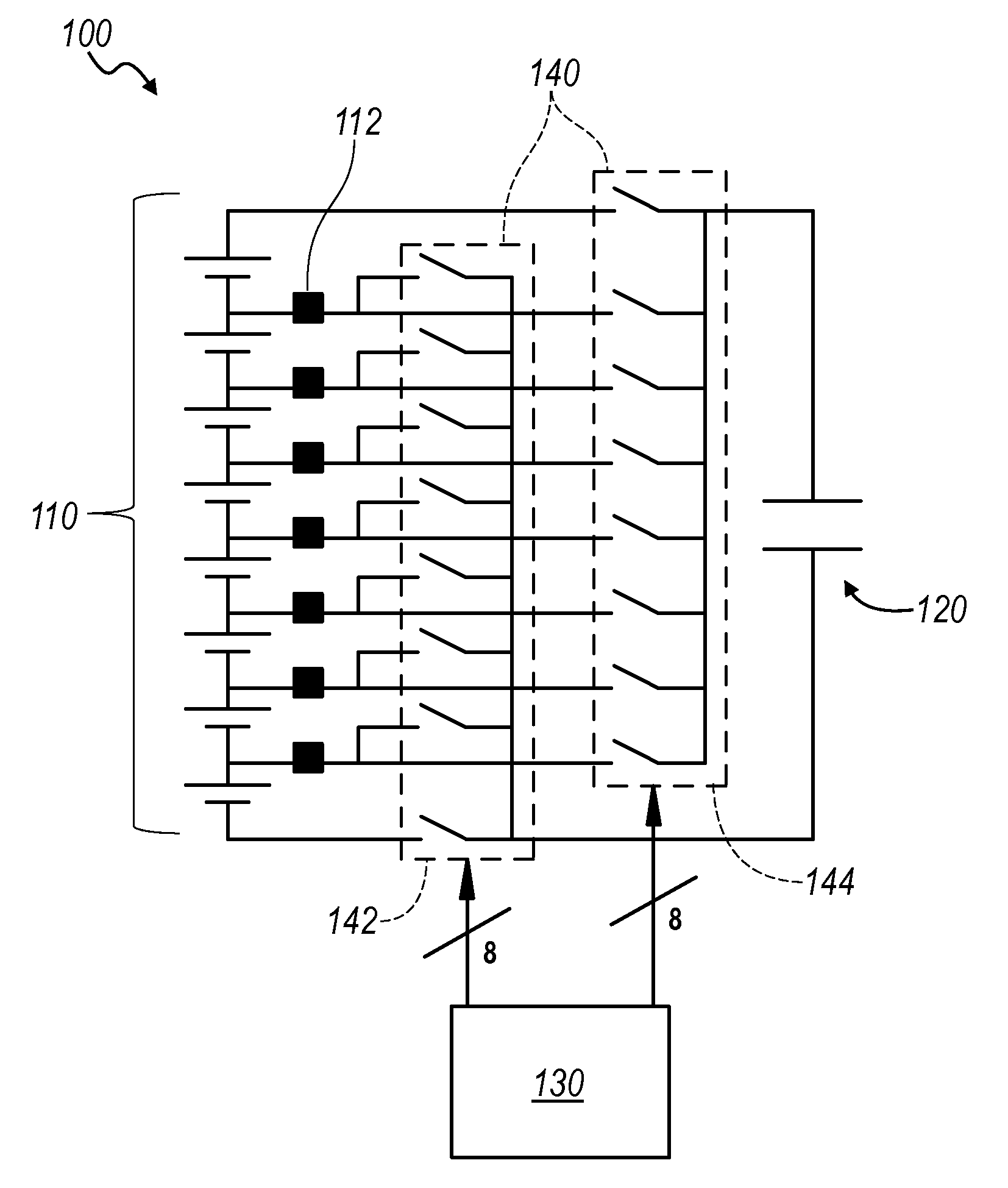
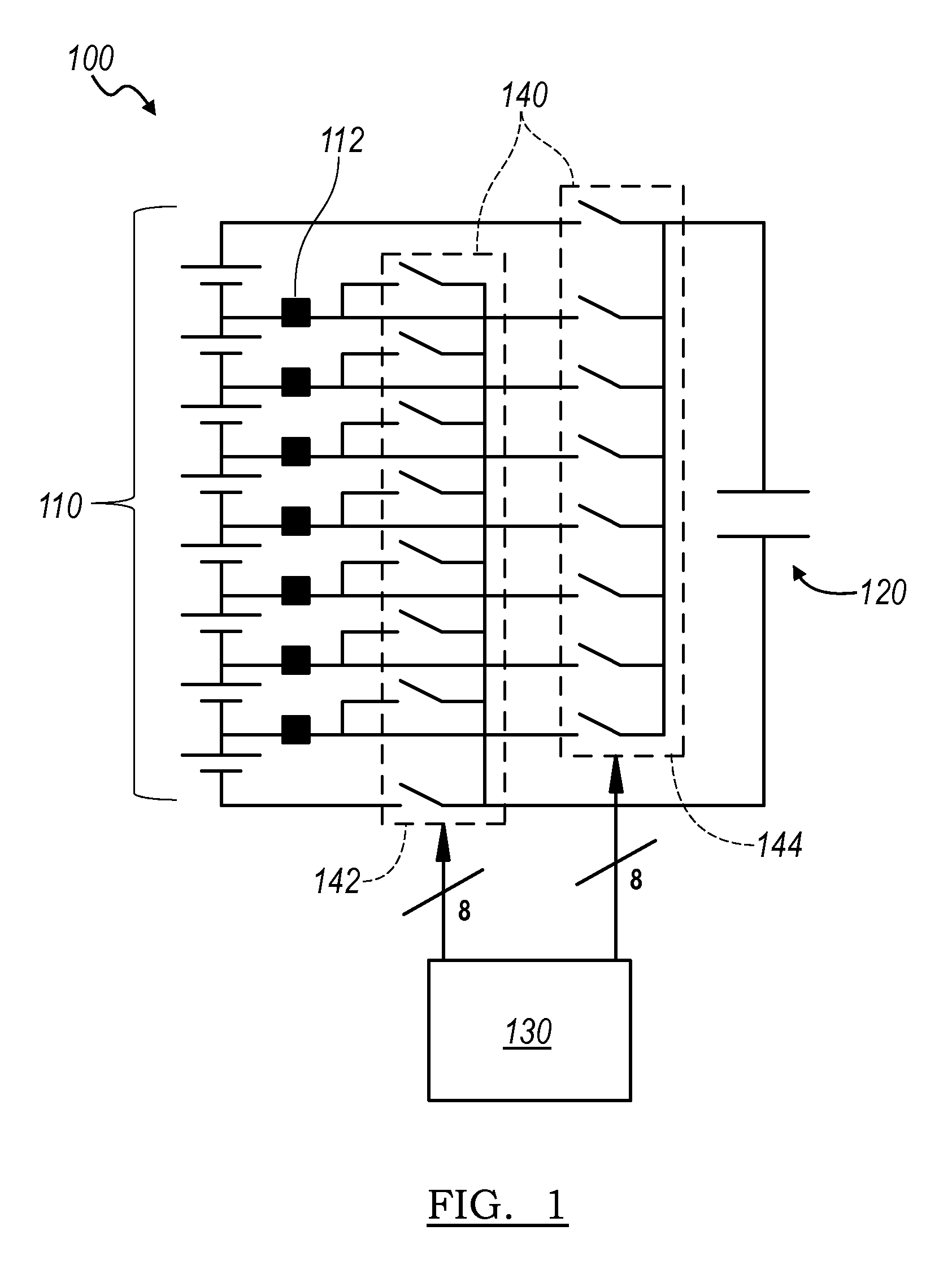
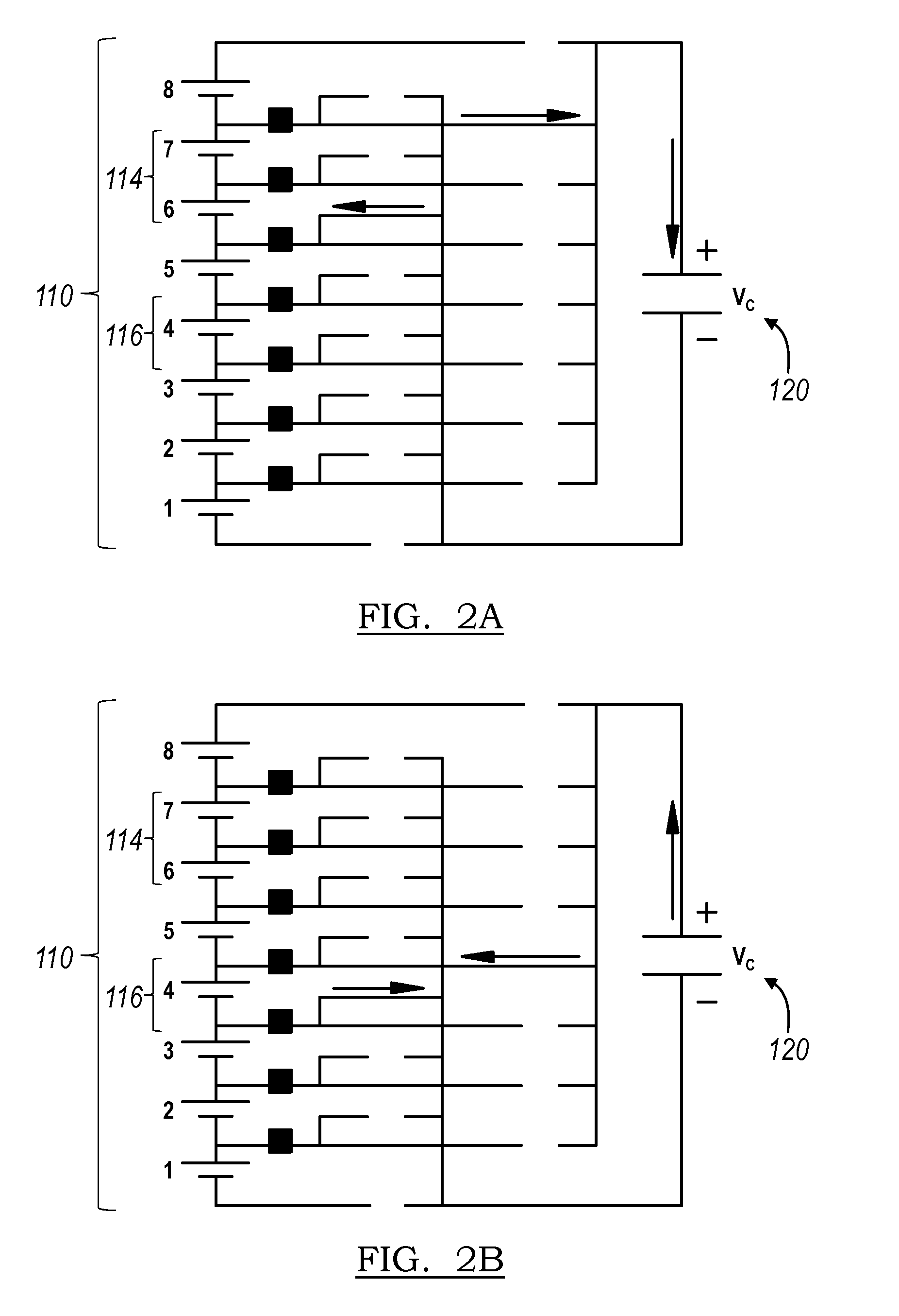
system of the preferred embodiments, the processor may select a combination of donor cells and receiver cells in a first mode where the number of donor cells and receiver cells are equal and in a second mode where the number of donor cells is greater than the number of receiver cells. In usage scenarios that require a faster speed of charge balancing, the processor may select a combination of donor cells and receiver cells according to the second mode. For example, a substantially large number of donor cells that are connected in series (for example, if the number of the plurality of cells is N, then the number of donor cells may be up to N cells) to charge the capacitor and a substantially small number of receiver cells that are connected in series (for example, one) to
discharge the capacitor. Thus, the voltage
potential difference between the donor cells connected in series and the capacitor is significantly high, increasing the initial
charge rate of the capacitor. The charged capacitor is then at a substantially higher voltage potential than the receiver cell, increasing the initial
discharge rate of the capacitor and substantially increasing the charge transfer rate between the cells within the battery pack. Additionally, the increased combined voltage potential of the donor cells allows for an increased amount of charge to be transferred to the receiver cells in a fixed-time
charge and discharge cycle of the capacitor, increasing the speed of charge balancing within the battery pack over existing charge balancing circuits by orders of magnitude. The processor may alternatively select any other suitable combination of donor cells and receiver cells to increase the charge transfer rate between cells.
[0009]With increased rate of charge transfer between the donor cells, the capacitor, and the receiver cells, there may be a decrease in
charge transfer efficiency between cells. For example, with the increased
charge current, energy may be lost through heat dissipated through the circuit. Thus, in usage scenarios that do not require a
high rate of charge transfer between cells, the processor may select a combination of donor cells and receiver cells according to the first mode. For example, one
donor cell and one receiver cell. This will result in a lower initial charge /
discharge rate of the capacitor, which may allow for an increase in
charge transfer efficiency between cells. Alternatively, the processor may select a combination of donor cells and receiver cells according to the second mode, but with a smaller difference between the number of donor and number of receiver cells. The processor may alternatively select any other suitable combination of donor cells and receiver cells to increase the charge
transfer efficiency between cells.
[0010]The charge balancing system of the preferred embodiments allows for increased flexibility in charge balancing. By allowing selection of combinations of donor cells and receiver cells of a first and a second mode, any number of and any of the plurality of cells may function as donor cells and receiver cells interchangeably and the rate of charge transfer and the efficiency of charge transfer between cells may be optimized for different usage scenarios, which may result in a more balanced and healthy battery pack.BRIEF DESCRIPTION OF THE FIGURES

