Eureka AIR delivers breakthrough ideas for toughest innovation challenges, trusted by R&D personnel around the world.

Flashing support cant for a wall assembly and associated method

Inactive Publication Date: 2013-09-03
TY DAS BUILDING PROD LLC
View PDF27 Cites 8 Cited by
  • Summary
  • Abstract
  • Description
  • Claims
  • Application Information

AI Technical Summary

Benefits of technology

The patent text describes a new invention that improves water management in building structures. By using a special metal or polypropylene member that is designed to guide water flow, the invention helps prevent harmful mold, dry rot, and other forms of damage to the structure. It also saves money for builders and homeowners by reducing the need for expensive repairs. The invention is easy to install and can be rotated for different applications. Overall, the invention provides better protection for the structure and reduces the risk of negative pitch or water damage.

Problems solved by technology

Such molds can, and have, caused a recognized and serious health threat to home owners and building occupants.
Since mold spores have been found to be a serious health risk of late, due to increased incidence of moisture ingress in newer construction systems, preventing moisture from entering the walls of homes and buildings is considered much more serious and widespread concern than it has previously.
However, this solution is costly because it is labor intensive.
Further, if the flashing is not properly installed, such as by a careless or unskilled worker, water can leak at a sagged and failed flashing and into the open upper end of the frame member.
One identified problem is where there would be a negative pitch back toward the interior side of the flashing assembly caused by construction irregularities.
While this method is used extensively below grade, the trades involved with installing flashing above grade often dispense with the mixed version of the cant in favor of none at all because of timing sensitivity in completing the installation and construction.

Method used


Image

  • Flashing support cant for a wall assembly and associated method
  • Flashing support cant for a wall assembly and associated method
  • Flashing support cant for a wall assembly and associated method

Examples


Embodiment Construction

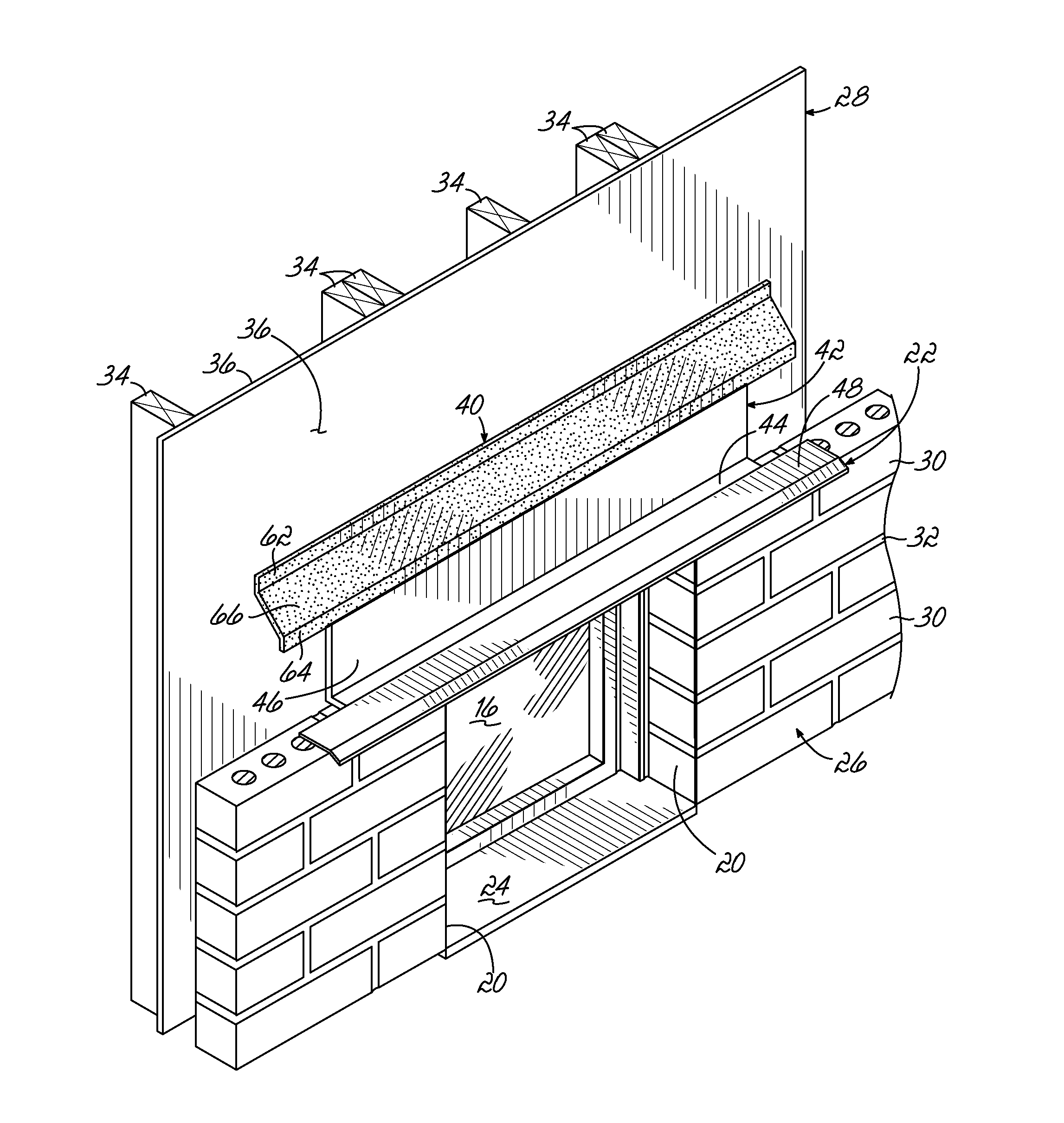
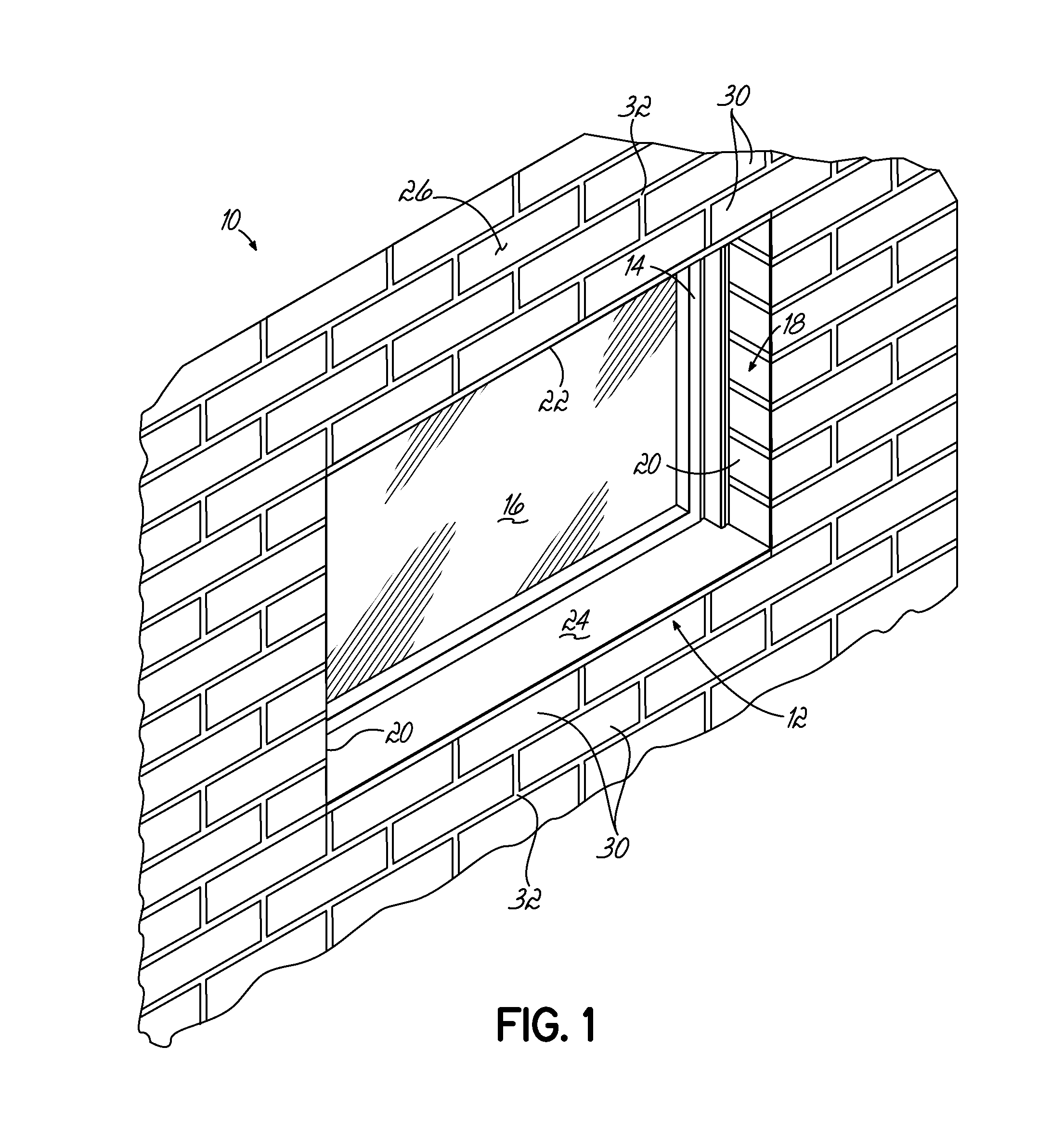
[0022]Referring to FIG. 1, an exemplary fixture installation 10 in a wall assembly 12 is shown. The exemplary fixture installation 10 includes a perimeter window frame 14, one or more window panes 16, and a window opening 18 in the wall defined by a pair of jambs 20 and a header 22 above and a sill 24 below the window frame 14. Although one example of a window installation and a wall assembly 12 is shown in FIG. 1, this invention is readily applicable for a variety of other construction wall environments, including, but not limited to, door installations, installations including a transition of the wall assembly from vertical to horizontal planes and bridging gaps between vertical wall components.

[0023]As shown more clearly in FIGS. 3-4, one embodiment of the wall assembly 12 for the exterior of a building is comprised of an exterior wall of masonry or brick veneer 26 and an interior wall 28. The brick veneer exterior wall 26 is constructed from a plurality of bricks or blocks 30 ar...


PUM


Abstract

In various embodiments, this invention includes a wall assembly having an interior generally vertical wall having a wall face, an exterior generally vertical wall confronting and being spaced from the wall face, and a generally horizontal ledge extending perpendicularly to the interior and exterior walls. A cant member is installed above grade on the wall assembly and has a upper portion, a lower portion and a cant portion intermediate the wall and lower portions. The upper portion is juxtaposed in face-to-face relation to the wall face and the lower portion is juxtaposed in face-to-face relation to the ledge with the cant portion extending between the wall and lower portions such that a flashing is supported by the cant and moisture on the wall face of the interior wall is diverted by the cant member along the cant portion toward the exterior wall and away from the wall assembly. The invention also extends to a cant member as described in various embodiments herein as well as a method of constructing a wall assembly.

Description

[0001]This claims the benefit of U.S. Provisional Patent Application Ser. No. 61 / 310,346, filed Mar. 4, 2010, and hereby incorporated by reference in its entirety.BACKGROUND OF THE INVENTION[0002]The invention relates generally to water management systems for reducing water intrusion in structures. More specifically, the invention relates to such systems and configurations for above grade installation in wall assemblies.[0003]Fungus and other molds having known health risks associated with them have been found growing within the walls of homes and buildings. Such molds can, and have, caused a recognized and serious health threat to home owners and building occupants. The growth of such molds can be facilitated by moisture seeping within the walls of homes and buildings. Conventionally, keeping moisture out of human-built structures has been an ongoing goal. Since mold spores have been found to be a serious health risk of late, due to increased incidence of moisture ingress in newer ...

Claims


Application Information

Patent Timeline
IPC IPC(8): E04B1/00
CPCE04B1/7046E04C2003/023
Inventor COLLINS, P. MICHAEL
Owner TY DAS BUILDING PROD LLC
Why Eureka
Eureka Blog
Learn More