
Bonding of thermoplastics

a thermoplastic and bonding technology, applied in the field of heater mats, can solve the problems of limited heating power known heater mats can produce, dielectric materials used in heater mats have limited operating temperatures, and the heater mats of this kind suffer from a number of problems, so as to achieve the effect of improving stability

Active Publication Date: 2013-09-03
GKN AEROSPACE SERVICES LTD
View PDF12 Cites 10 Cited by
  • Summary
  • Abstract
  • Description
  • Claims
  • Application Information

AI Technical Summary

Benefits of technology

The patent text describes a heater mat that uses thermoplastic materials like PEEK, which have excellent mechanical properties and can withstand higher temperatures than traditional dielectric materials. This allows the heater mat to output more heating power. The adhesive receiving layer is partially embedded within the thermoplastic layer, allowing for strong attachment while still receiving an adhesive for attaching to another object. The heater mat also includes a stabilising layer embedded in the thermoplastic layer to improve stability during the heating process. The stabilising layer can be sprayed onto the thermoplastic layer using metal spraying technology.

Problems solved by technology

Heater mats of this kind suffer from a number of problems.
A first problem is that dielectric materials hitherto used in heater mats have limited operating temperatures.
The maximum operating temperatures of hitherto used dielectrics limits the amount of heating power known heater mats can produce.
Additionally, the limited temperatures that hitherto used dielectrics limits can withstand exacerbate problems associated with the development of “hot spots” in a heater mat (for example due to internal short circuits or other failures), potentially leading to catastrophic failure.
Another problem is that the condition of some dielectric materials such as Kapton can deteriorate over time.
This can lead to failure of the heater mat on exposure of the thermoelectric heater element to moisture, and / or can lead to short circuiting of the thermoelectric heater element on a metallic surface to which the heater mat is applied.

Method used


Image

  • Bonding of thermoplastics
  • Bonding of thermoplastics
  • Bonding of thermoplastics

Examples


Embodiment Construction

[0032]Particular embodiments will now be described by way of example only in the following with reference to the accompanying drawings.

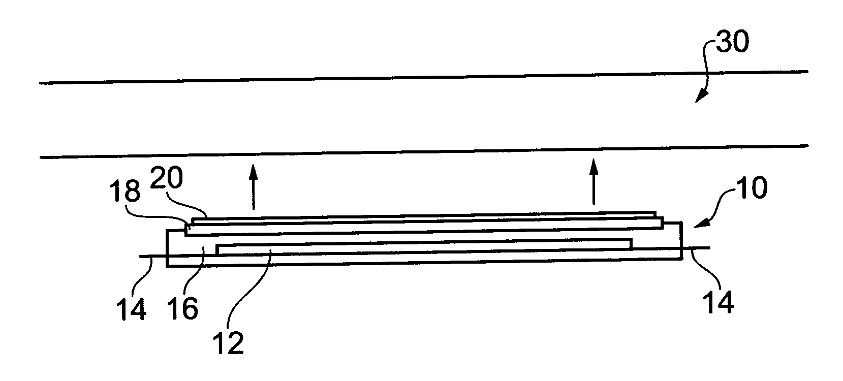
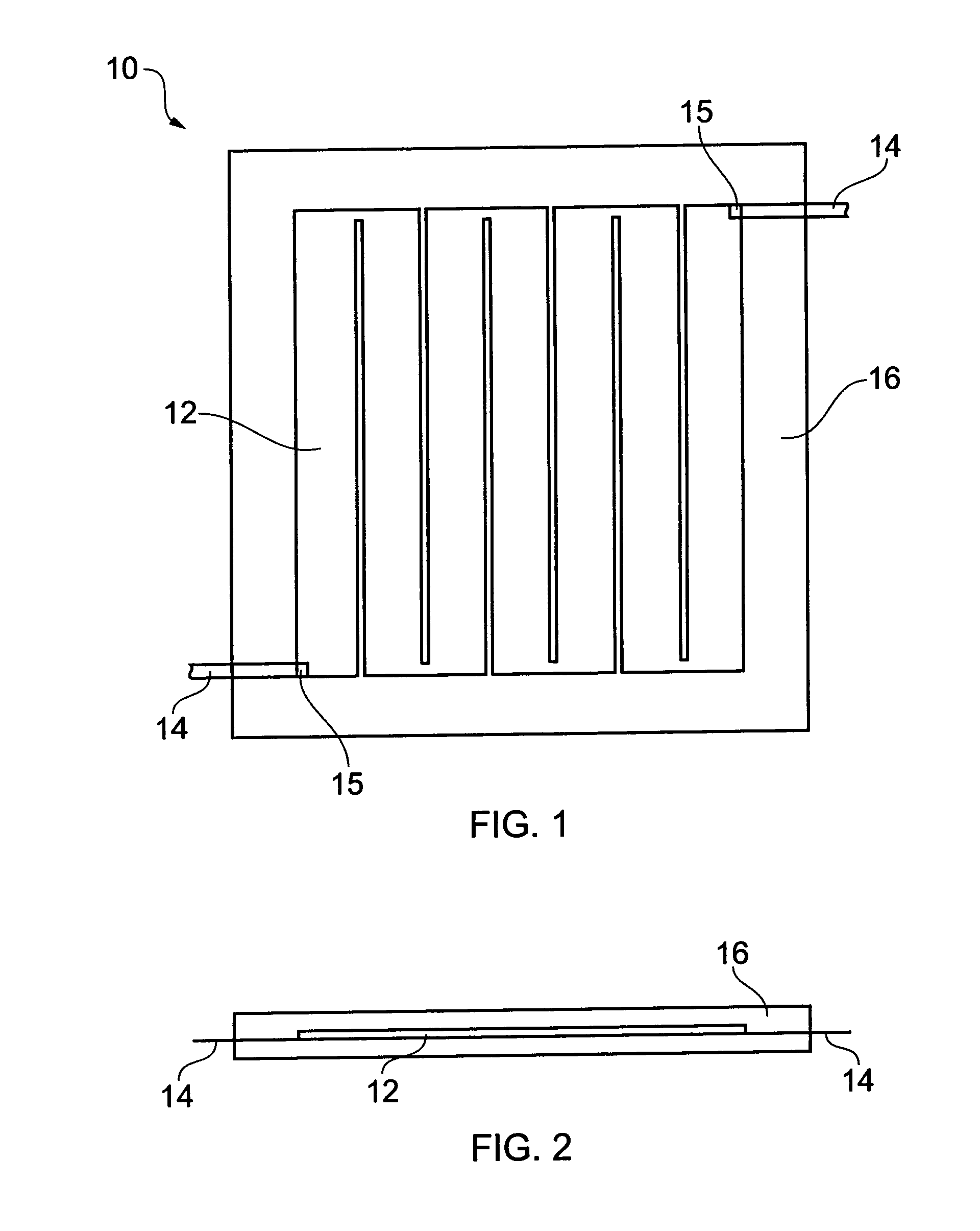
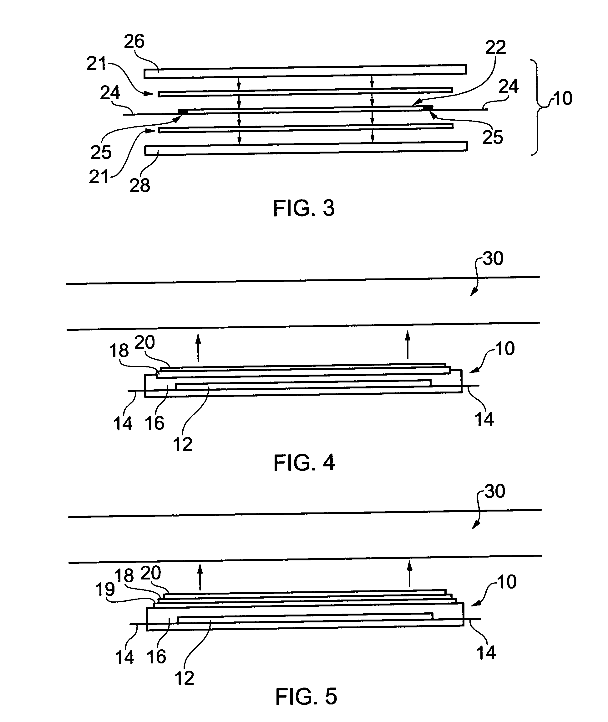
[0033]According to an embodiment of this invention, there can be provided an aircraft leading edge ice protection system. The system includes a thermoelectric heater mat that includes a thermoplastic layer within which is embedded an electrically resistive heater element. The heater mat is provided with one or more adhesive receiving layers to facilitate attachment of the mat to a surface using an adhesive. Embodiments of this invention also provide methods of making such an ice protection system.

[0034]Thermoplastics are characterised by their material properties as a function of temperature. In particular, thermoplastic materials are plastic (deformable) in a temperature between an upper transition temperature Tm and a lower transition temperature Tg. Above Tm, thermoplastic materials melt to form a liquid. Below Tg they enter a brittle, glassy stat...


PUM

PropertyMeasurementUnit
operating temperatureaaaaaaaaaa
Young's modulusaaaaaaaaaa

Abstract

An aircraft leading edge ice protection system. The system includes: a thermoelectric heater mat (10) attachable to a leading edge component of an aircraft, the heater mat comprising: an electrically resistive heater element (12, 22) embedded in a thermoplastic layer (16, 26, 28), the thermoplastic layer having a first surface; and a first adhesive (20) receiving layer (18) located on a surface of the thermoplastic layer. A method of making an aircraft leading edge ice protection system, the method comprising: making a thermoelectric heater mat by embedding an electrically resistive heater element in a thermoplastic layer, the thermoplastic layer having a first surface; and locating a first adhesive receiving layer on a surface of the thermoplastic layer.

Description

CROSS REFERENCE TO RELATED APPLICATIONS[0001]This application represents the national stage application of International Application PCT / GB2008 / 003500 filed 15 Oct. 2008, which claims priority of Great Britain Patent Application No. 0720415.9 filed 18 Oct. 2007, which are incorporated herein by reference in their entirety for all purposes.BACKGROUND OF THE INVENTION[0002]This invention relates to a heater mat and a method of making a heater mat.[0003]Known heater mats such as those that can be used as part of a de-icing system for a leading edge of an aircraft include a thermoelectric heater element and one or more layers of a dielectric material such as Kapton. The dielectric protects the thermoelectric heater element and can serve to electrically insulate it from a metallic surface (such as an inner surface of an aircraft leading edge) to which the heater mat is to be applied.[0004]Heater mats of this kind suffer from a number of problems.[0005]A first problem is that dielectric m...

Claims


Application Information

Patent Timeline
Patent Type & Authority Patents(United States)
IPC IPC(8): B64D15/12
CPCH05B3/36B64D15/12H05B3/286H05B2203/003H05B2203/013H05B2203/017Y10T156/10H05B3/06
Inventor ATKINSON, JAMES WILLIAM
Owner GKN AEROSPACE SERVICES LTD
Learn More