Soil compaction device having a disconnectable fuel line

a fuel line and soil compaction technology, applied in the direction of liquid fuel feeders, diaphragm valves, soil preservation, etc., can solve the problems of unfavorable fuel flow interruption and increase the operational reliability of soil compaction devices, and achieve the effect of high operational reliability

Inactive Publication Date: 2013-09-03
BOMAG
View PDF17 Cites 0 Cited by
  • Summary
  • Abstract
  • Description
  • Claims
  • Application Information

AI Technical Summary

Benefits of technology

[0004]It is therefore an object of the present invention to provide a soil compaction device with which a high level of operational reliability can be ensured.
[0006]The clamping occurs when the flexible section of the fuel line is compressed or squeezed by application of a force (clamping force) at a position provided for this purpose for interrupting the fuel flow. After removing the force, the compressed region of the fuel line will expand again as a result of elastic restoring forces and will release the fuel flow again. Whereas the valve devices known from the prior art are highly sensitive to shocks, vibrations and gumming (which leads to leakages, for example), the solution in accordance with the principles of the present invention is advantageously characterized in that it is robust in numerous ways. Furthermore, an undesirable fuel flow can reliably be interrupted, so that the operational reliability of the soil compaction device is increased considerably. Furthermore, a valve device as known from the prior art as described above can be omitted, so that costs can be saved. The proposed solution is convincingly simple which requires only few components and is extremely robust.
[0008]The flexible section preferably comprises a hose section which is made of a fuel-resistant and weatherproof material. In the case of aging or material fatigue, the respective section can be exchanged rapidly and easily even by untrained staff on site, e.g., at the construction site. This also contributes to an increased operational reliability of the soil compaction device.
[0010]According to one embodiment of the present invention, the gas actuation device and / or the start-stop device comprises a pivotable actuating lever (gas lever and / or on-off lever) or the like which can be manually actuated by the operator and which is able to mechanically act on the elastically flexible section of the fuel line via a lever in order to disconnect the fuel flow through the fuel line. The lever mechanism is simply formed by an extension of the actuating lever protruding beyond the pivot joint. Preferably, the actuating lever is integrally arranged with the extension. The extension can act either directly or indirectly on the elastically flexible section of the fuel line in order to produce the clamping. It is provided that, for the indirect clamping, at least one roll or roller is arranged on the extension, which roll or roller acts on the elastically flexible section of the fuel line in order to enable disconnecting the fuel flow through the fuel line. Excessive frictional and thrust forces on the outside jacket of the fuel line can be avoided by using a roll or a roller, which forces could lead to wear and tear and to damage. The roll or the roller is therefore used as a wear-reducing element.
[0013]According to one embodiment of the present invention, the clamping device is arranged to clamp and subsequently release at least one elastically flexible section of a fuel line arranged between the tank container and the internal combustion engine, and simultaneously at least one vent line. Such a vent line is connected to an air port and / or vent hole of the tank container. The escape of fuel during the deactivated internal combustion engine, e.g., during the transport of the soil compaction device, can thus effectively be prevented, while the required venting of the tank container in operation remains ensured. The simultaneous closing of the vent line also prevents the escape of hazardous fuel vapors. More than two lines can be disconnected according to the same principle.

Problems solved by technology

Furthermore, an undesirable fuel flow can reliably be interrupted, so that the operational reliability of the soil compaction device is increased considerably.

Method used


Image

  • Soil compaction device having a disconnectable fuel line
  • Soil compaction device having a disconnectable fuel line
  • Soil compaction device having a disconnectable fuel line

Examples


first embodiment

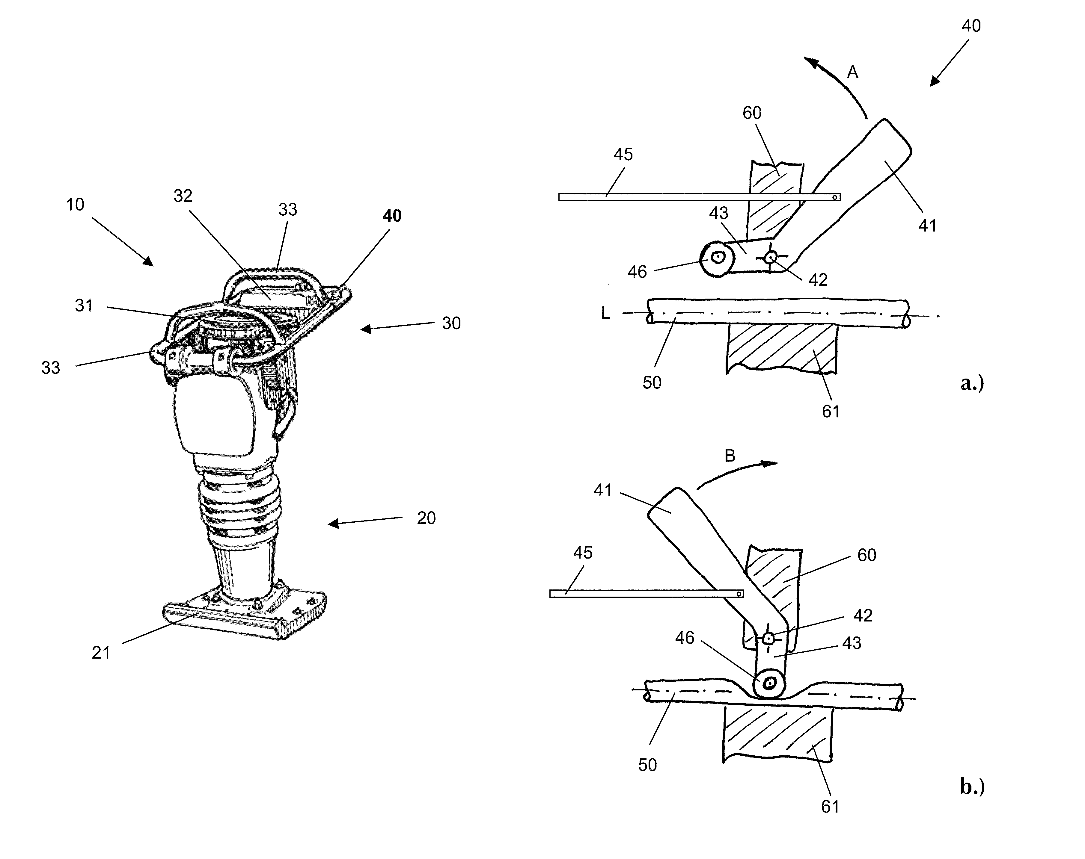
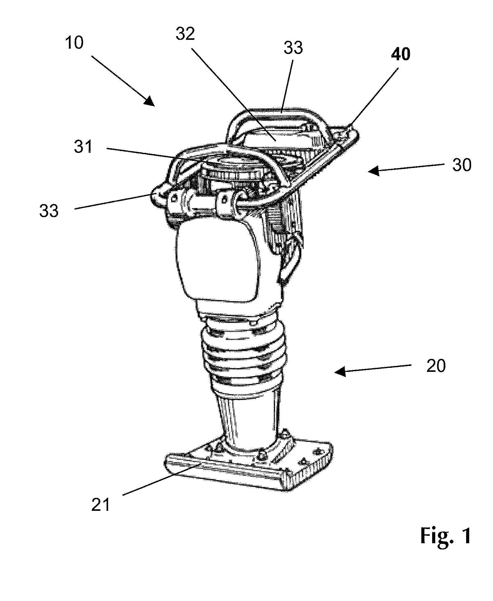
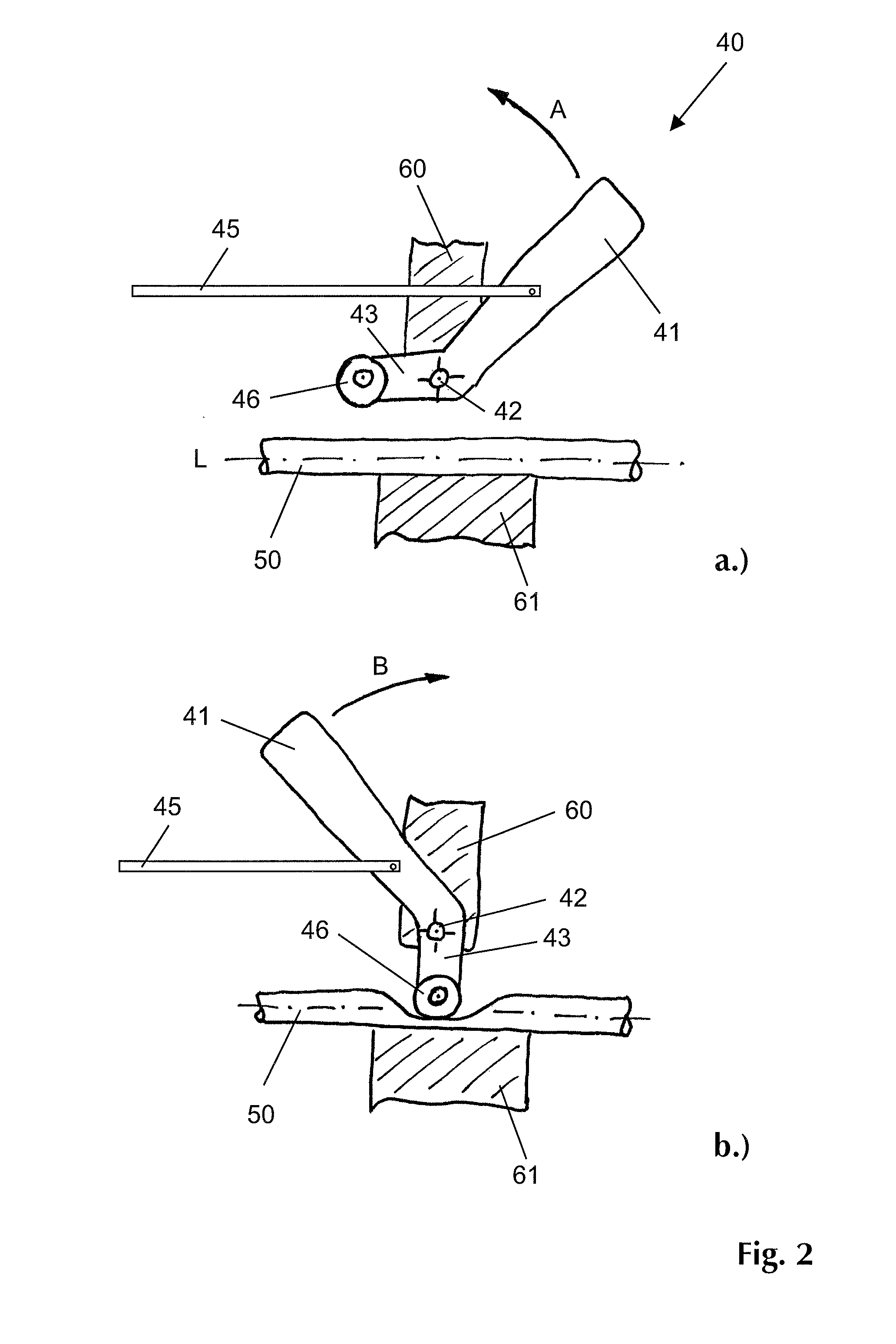
[0026]FIG. 3 shows another embodiment of the present invention. The same components and / or components with the same function are designated with the same reference numerals. The illustrations show the same actuating lever 41 in a first operating position (FIG. 3a), in a second operating position or idle or start position (FIG. 3b), and in a stop position (FIG. 3c). Only the relevant differences compared to FIG. 2, will be described below.

[0027]Deviating from the first embodiment of FIG. 2, the actuating lever 41 is provided with an eccentric cam 44 which in the stop position (FIG. 3c) presses the flexibly elastic section 50 of the fuel line against the rigid clamping jaw 61 by means of a movable pressure element or clamping element 70, by means of which the fuel flow through the fuel line is disconnected. The movable pressure element 70 transmits the clamping force applied by the cam 44 and simultaneously absorbs the frictional and / or thrust forces resulting from the relative moveme...

second embodiment

[0028]FIG. 4 shows a further embodiment of the present invention. The same components and / or components with the same function are designated with the same reference numerals. The illustration shows the actuating lever 41 in a first operating position which corresponds to the operating position as shown in FIG. 3a. Only the relevant differences compared to FIG. 3, will be described below.

[0029]Deviating from the second embodiment of FIG. 3, two line sections 50 and 51 are arranged between the movable pressure element 70 and the clamping jaw 61. The section 50 concerns a section of the fuel line which connects the tank container 32 with the internal combustion engine 31, as already described above. The section 51 concerns the section of a vent line which is used for venting and / or airing the tank container 32. Both line sections 50 and 51 are simultaneously clamped by means of the cam 44 and the movable clamping element 70 when the actuating lever 41 is moved from the illustrated ope...


PUM


Abstract

The present invention relates to a soil compaction device, in particular such as a tamper or a vibration plate device, having an internal combustion engine and a tank container for receiving fuel for the operation of said internal combustion engine. According to the present invention, there is at least one clamping device on the soil compaction device which has a mechanical effect on an elastically flexible section of a fuel line arranged between the tank container and the internal combustion engine in order to be able to disconnect the fuel flow, wherein the clamping device is mechanically coupled to a manually actuated gas actuation apparatus and / or start-stop apparatus for the internal combustion engine, or integrated therein, wherein at least one roll or roller is arranged on the extension which has an effect on the elastically flexible section of the fuel line in order to disconnect the fuel flow.

Description

CROSS-REFERENCE TO RELATED APPLICATIONS[0001]This application is a submission under 35 U.S.C. §371 of International Application No. PCT / EP2011 / 000309, filed Jan. 25, 2011, which claims priority to German Application No. 10 2010 005 597.2, filed Jan. 25, 2010, the disclosures of which are hereby expressly incorporated by reference herein in their entireties.FIELD OF THE INVENTION[0002]The present invention relates to a soil compaction device with an internal combustion engine and a tank container for receiving fuel for the operation of the internal combustion engine. The soil compaction device preferably is a hand-operated soil compaction device such as a tamper, a vibration plate device or the like.BACKGROUND OF THE INVENTION[0003]During transport or prolonged storage of such a soil compaction device, fuel from the tank container can reach the internal combustion engine, which is undesirable. Especially susceptible are internal combustion engines with a diaphragm carburetor device, ...

Claims


Application Information

Patent Timeline
Patent Type & Authority Patents(United States)
IPC IPC(8): E01C19/30F16K7/06
CPCE01C19/35F02M37/007E02D3/074
Inventor LAUGWITZ, NIELS
Owner BOMAG
Why Eureka
Try Eureka