Power plug locking device having a control unit for moving a lock member between different positions

a technology of locking device and power plug, which is applied in the direction of locking application, coupling device connection, transportation and packaging, etc., can solve the problems of user error, lengthen charging time, and remove the power plug to steal electricity

Inactive Publication Date: 2013-09-03
KK TOKAI RIKA DENKI SEISAKUSHO
View PDF9 Cites 38 Cited by
  • Summary
  • Abstract
  • Description
  • Claims
  • Application Information

AI Technical Summary

Benefits of technology

[0009]One aspect of the present invention is a power plug locking device that prevents unauthorized removal of a power plug from an inlet. The power plug locking device includes a lock member arranged in the inlet. The lock member blocks removal of the power plug when the power plug is connected to the inlet. A drive unit moves the lock member. A control unit controls the drive unit to move the lock member from an operational start position to an operational end position. The control unit obtains positional information of the lock member. A movable mechanism mechanically moves the lock member from a usable position, which is a position before the operational end portion, to the operational end position. The control unit controls the drive unit based on the positional information to move the lock member to the usable position. The control unit stops the drive unit when the lock member reaches the usable position. The movable mechanism mechanically moves the lock member from the usable position to the operation end position.

Problems solved by technology

This lengthens the charging time.
Thus, when a user leaves the vehicle while the battery is being charged, someone may remove the power plug to steal electricity.
In such a case, the user may erroneously be notified that the lock bar has reached the end position.

Method used


Image

  • Power plug locking device having a control unit for moving a lock member between different positions
  • Power plug locking device having a control unit for moving a lock member between different positions
  • Power plug locking device having a control unit for moving a lock member between different positions

Examples


Embodiment Construction

[0021]One embodiment of a power plug locking device according to the present invention will now be described with reference to FIGS. 1 to 7.

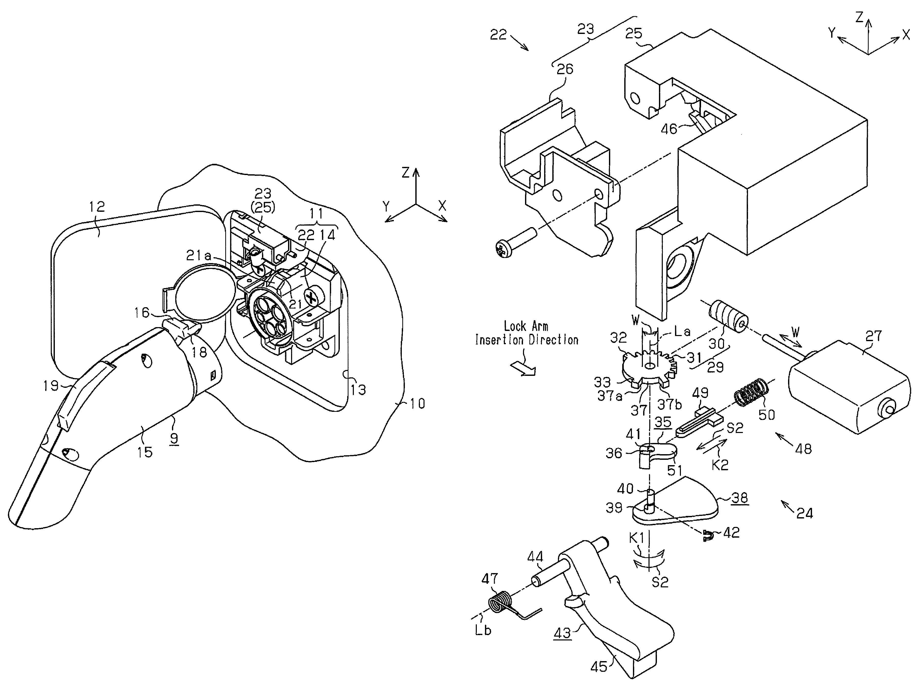
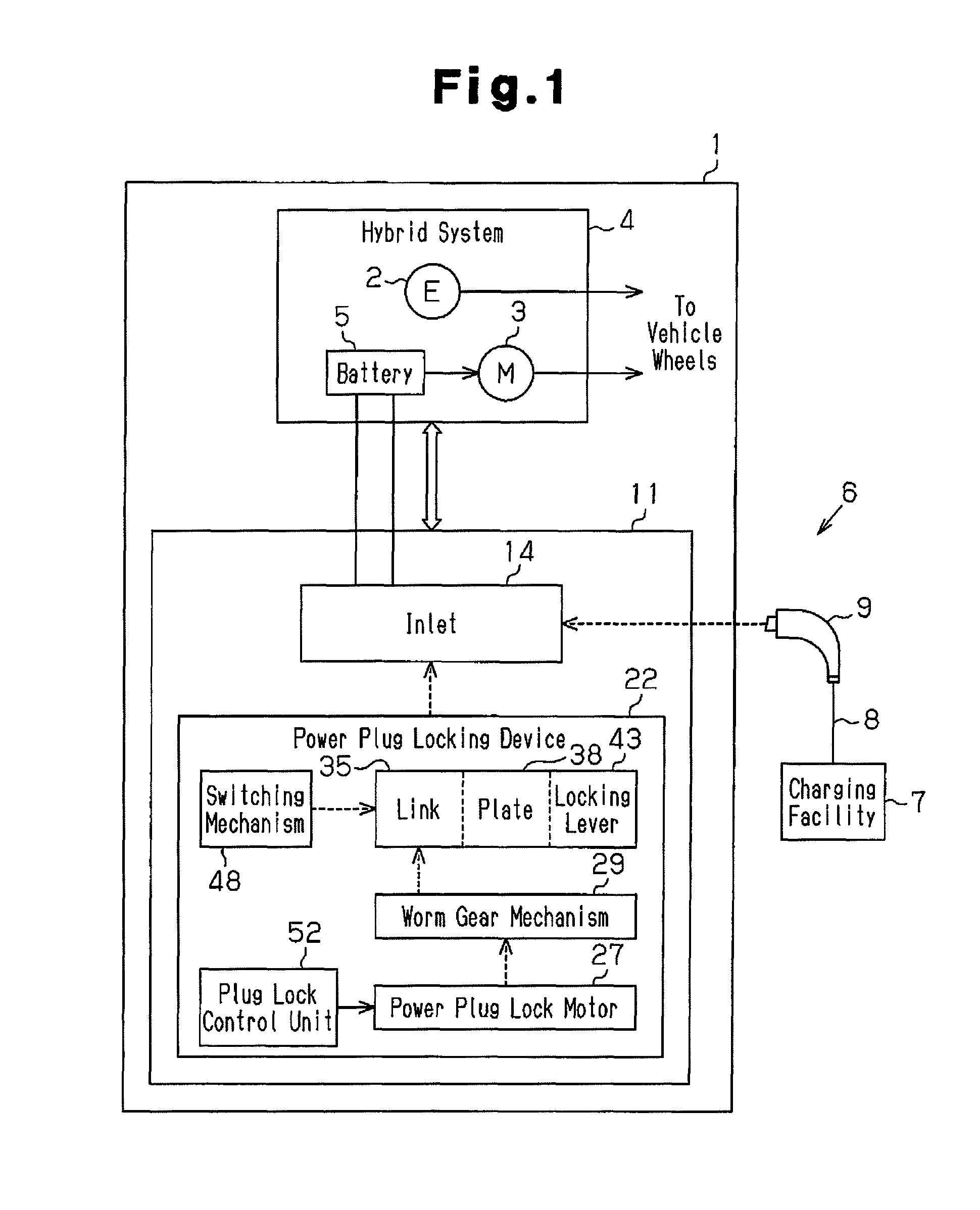
[0022]Referring to FIG. 1, a hybrid vehicle 1 includes an engine 2 and a motor 3 arranged in a vehicle body 10. The engine 2 and the motor 3 form a hybrid system 4 and generate power to rotate vehicle wheels. The hybrid system 4 includes a battery 5, which serves as a power source for the motor 3. The vehicle 1 also includes a charge system 6 that charges the battery 5 with an external power supply. The charge system 6 uses a charging facility 7, such as a charging station or a residential power outlet. The charging facility 7 provides a charge cable 8 and a power plug 9, which is arranged on a distal end of the charge cable 8. The power plug 9 is connected to the vehicle 1 to charge the battery 5.

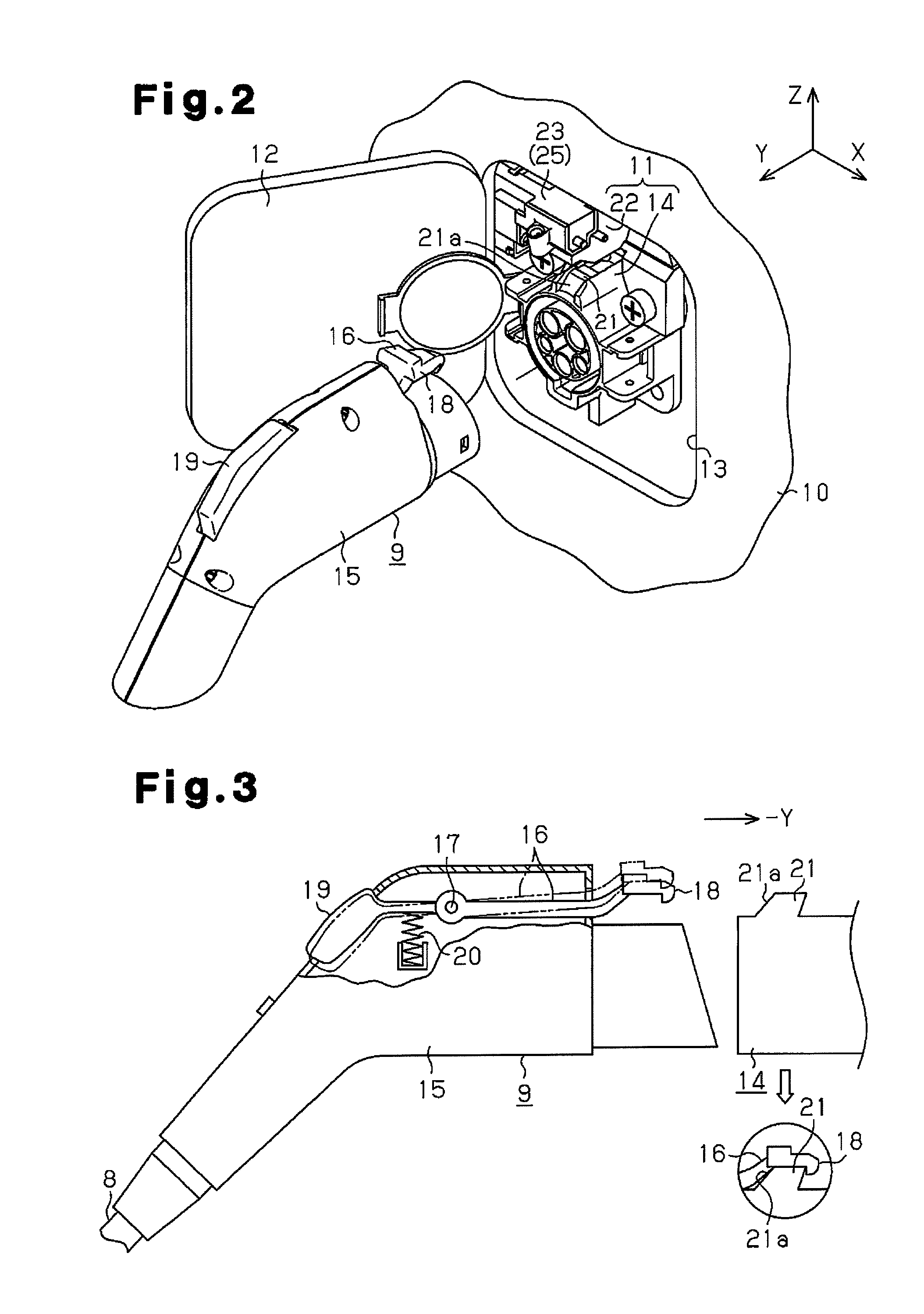
[0023]Referring to FIGS. 1 and 2, the vehicle body 10 includes a lid 12, which opens and closes an accommodation compartment 13. A power reception con...


PUM


Abstract

When a power plug locking device moves a plate to a lock position or unlock position, the plate is rotated toward an operational end position with a power plug lock motor while the current of the motor is detected. When the plate comes into contact with a switching piece of a switching mechanism, the switching piece applies a load to the plate. When the current flowing through the motor becomes greater than or equal to a threshold, the supply of power to the power plug lock motor is stopped. Then, switching load of the switching mechanism 48 pushes and moves the disk to an operational end position (lock position or unlock position).

Description

CROSS-REFERENCE TO RELATED APPLICATIONS[0001]This application is based upon and claims the benefit of priority from prior Japanese Patent Application No. 2011-073127, filed on Mar. 29, 2011, the entire contents of which are incorporated herein by reference.BACKGROUND OF THE INVENTION[0002]The present invention relates to a power plug locking device that locks a power plug to an object, such as a vehicle, and prevents unauthorized removal of the power plug from the object.[0003]Over these recent years, consumers have become conscious of environmental problems. Thus, vehicles that emit less carbon dioxide such as hybrid vehicles and electric vehicles have become popular. Such vehicles are driven by a battery-powered motor. When such a vehicle travels over a long distance and the state of charge of the battery becomes low, the battery must be charged (refer to Japanese Laid-Open Patent Publication No. 9-161898).[0004]The charging of a battery involves an electrolytic reaction of compou...

Claims


Application Information

Patent Timeline
Patent Type & Authority Patents(United States)
IPC IPC(8): H01R13/62B60L11/18E05B83/00H01R13/639H01R13/64
CPCH01R13/6275H01R13/6397B60L11/1818B60L11/14H01R2201/26Y02T10/7005Y02T90/14Y02T10/70Y02T10/7077Y02T90/16B60L2240/662B60L2270/34Y02T10/7291B60L2270/32B60L50/16B60L53/16Y02T10/7072Y02T10/72
Inventor KURUMIZAWA, NAOTOKATAGIRI, TOSHIHARU
Owner KK TOKAI RIKA DENKI SEISAKUSHO
Why Eureka
Try Eureka