
UV fluid sterilizer suitable to sterilize fluid having poor UV transmission

a fluid sterilizer and ultraviolet light technology, applied in the field of ultraviolet light, can solve the problems of insufficient sterilization by conventional art and high energy cost, and achieve the effect of increasing the scanning efficiency of the ultraviolet light, effectively sterilizing the fluid, and smoothing the flow of the fluid

Active Publication Date: 2013-09-03
LEE SUNG CHUL +2
View PDF9 Cites 7 Cited by
  • Summary
  • Abstract
  • Description
  • Claims
  • Application Information

AI Technical Summary

Benefits of technology

The UV fluid sterilizer described in this patent makes fluid flow in a thin film shape while creating a turbulent flow, which improves the scanning efficiency of the UV lamp. The UV is emitted both inside and outside of the fluid, increasing the surface area that can be sterilized. The flow of the fluid is made smoother by a UV transmission contraction film, and small impurities in the fluid are caught and removed by the coil spring, increasing the overall sterilization efficiency.

Problems solved by technology

When the sterilization on the fluid by means of heat is performed, over energy costs a lot, and lots of side effects occur as some components in the fluid is destroyed by high heat.
In order to prevent the above mentioned problems, the sterilization of the microorganism is desperately needed, but the conventional art does not fully perform the sterilization by way of the UV.

Method used


Image

  • UV fluid sterilizer suitable to sterilize fluid having poor UV transmission
  • UV fluid sterilizer suitable to sterilize fluid having poor UV transmission
  • UV fluid sterilizer suitable to sterilize fluid having poor UV transmission

Examples


Embodiment Construction

[0025]The embodiments of the present invention will be described with reference to the accompanying drawings. The following embodiments are provided only for the sake of illustrative purposes, and an ordinary person in the art can modify or change within the scopes that the technical concepts do not change. So, it should be interpreted that the scope of the present invention does not limit the following embodiments.

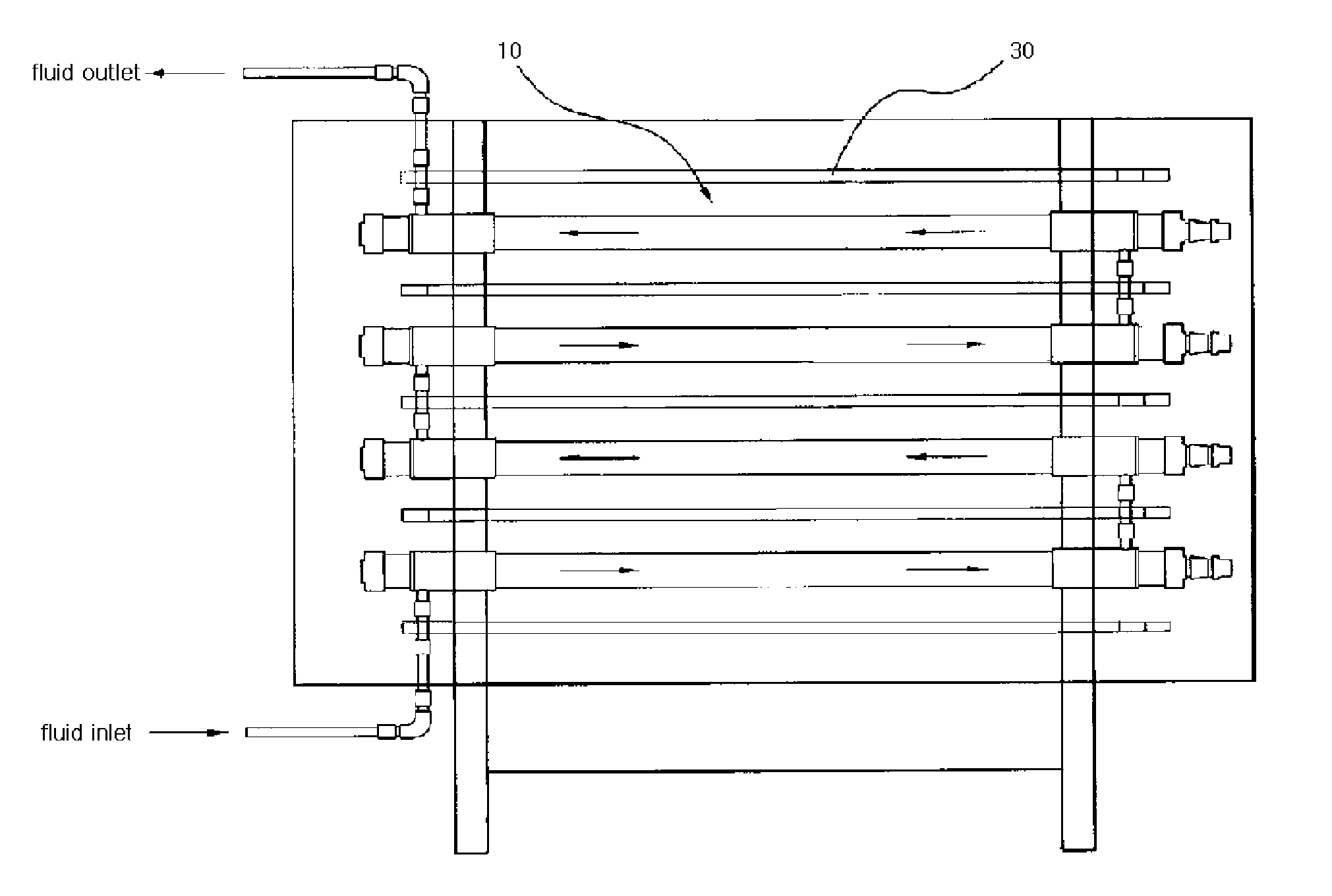
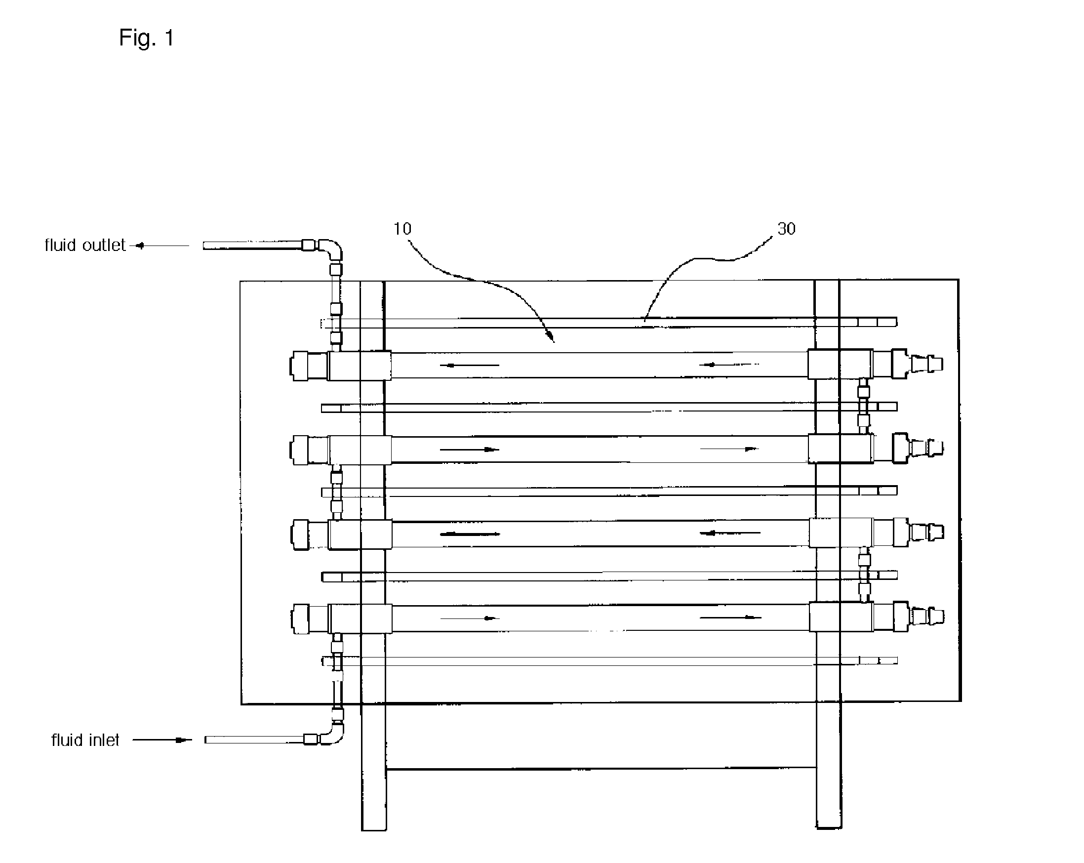
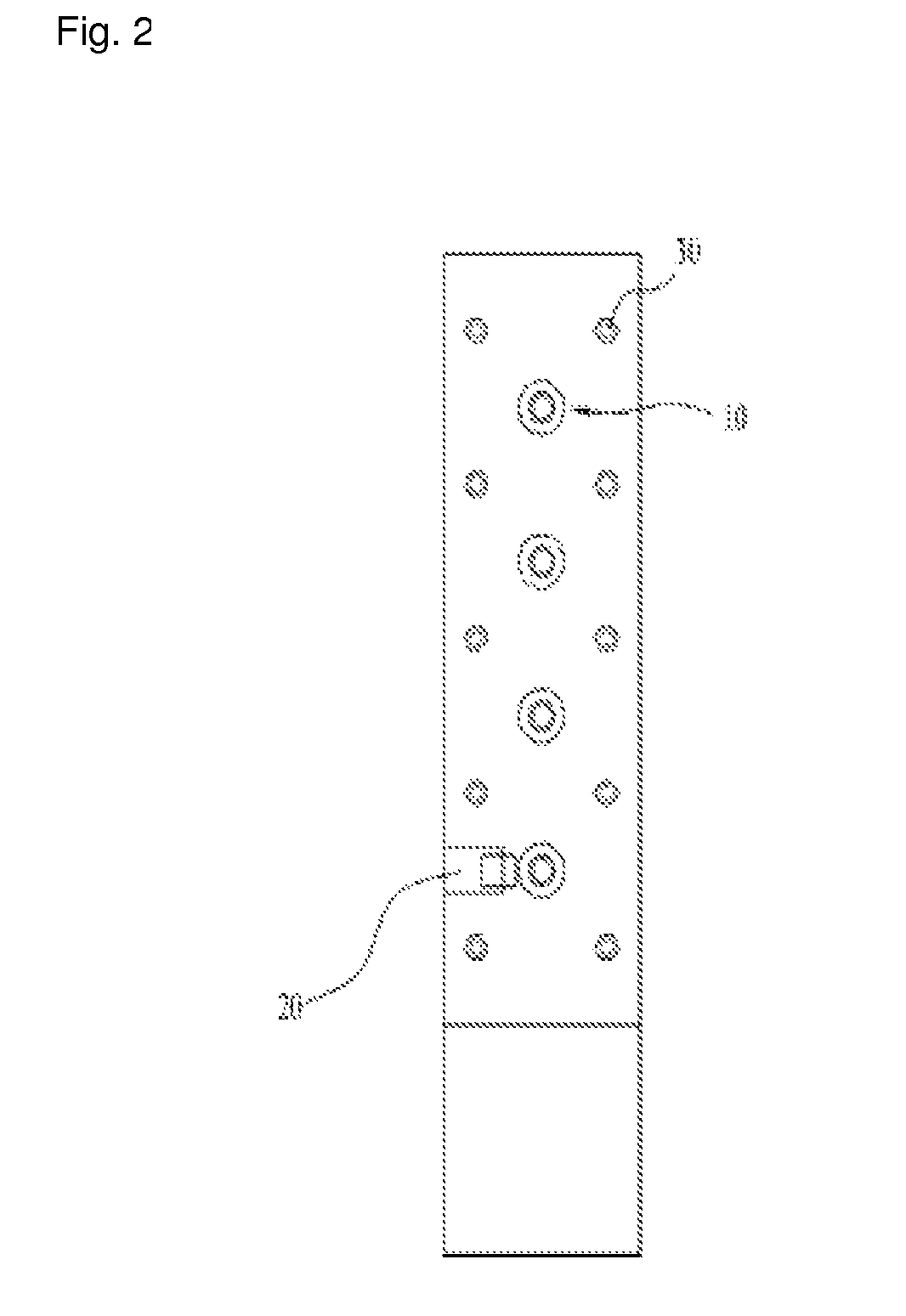
[0026]FIGS. 1 and 2 are schematic front and side views of a UV fluid sterilizer according to an embodiment of the present invention, and FIG. 3 is a cross sectional view shown by enlarging a UV sterilization unit, and FIG. 4 is a vertical cross sectional view of FIG. 3.

[0027]The UV fluid sterilizer according to an embodiment of the present invention features in that a plurality of UV sterilization units 10 are connected in series or in parallel. When the UV sterilization units 10 are connected in series, it helps enhance a sterilization efficiency, and when they are conne...


PUM

PropertyMeasurementUnit
wavelengthsaaaaaaaaaa
Reynold's numberaaaaaaaaaa

Abstract

The present invention relates to a UV fluid sterilizer, which is suitably formed to sterilize fluid having poor UV transmission. According to the present invention, the UV fluid sterilizer includes a plurality of UV sterilization units. The UV sterilization units include: small quartz tubes; inside UV lamps mounted in the small quartz tubes for radiating UV rays at the inside of fluid; large quartz tubes concentrically mounted outside the small quartz tubes for forming the flow spaces of the fluid; spring type coils spirally fixed to the outer diameter surfaces of the small quartz tubes for applying rotation force to the fluid; and UV transmission shrinks films for fixing the spring type coils to the outer diameter surfaces of the small quartz tubes in close contact and preventing foreign substances from being trapped in the flow spaces of the fluid, and are characterized in that a plurality of outside UV lamps are provided outside the large quartz tubes for radiating UV rays to the fluid, which flows through the UV sterilization units, from the outside.

Description

RELATED APPLICATIONS[0001]This application is a 371 application of International Application No. PCT / KR2010 / 007597, filed Nov. 1, 2010, which in turn claims priority from Korean Patent Application No. 10-2010-0031781, filed Apr. 7, 2010, each of which is incorporated herein by reference in its entirety.TECHNICAL FIELD[0002]The present invention relates to a UV (Ultraviolet ray) fluid sterilizer, and in particular to a UV fluid sterilizer which makes it possible to effectively sterilize a fluid which has a low UV transmissivity.BACKGROUND ART[0003]The UV sterilization is directed to a physical sterilization method using light and is concerned on a technology killing microorganism by preventing it from growing and differentiating in such a way to destroy microorganism DNA information by means of the operations of 254 nm wavelengths in UV waves.[0004]The UV sterilization way has been generally used for the sake of the sterilization of microorganism in fluid (or waterborne microorganism...

Claims


Application Information

Patent Timeline
Patent Type & Authority Patents(United States)
IPC IPC(8): C02F1/32A61L2/10G01N21/33
CPCA23L3/28C02F1/325A61L2/10C02F1/72C02F2201/3227C02F2303/04C02F2301/024C02F2301/026
Inventor LEE, SUNG CHULKIM, JIN AUCKKIM, YU SUP
Owner LEE SUNG CHUL
Learn More