
Systems for relieving pressure sores and methods therefor

a technology of pressure sores and systems, applied in the field of medical devices, can solve the problems of pressure sores that are not only very painful, prone to infection, and achieve the effect of lowering the pressure threshold value associated with them

Inactive Publication Date: 2013-09-10
TURO ANTHONY MICHAEL +3
View PDF23 Cites 6 Cited by
  • Summary
  • Abstract
  • Description
  • Claims
  • Application Information

AI Technical Summary

Benefits of technology

[0015]In one embodiment, after a patient is positioned atop a surface, the system controller preferably analyzes data associated with the patient to develop a baseline for the patient. The system controller may be used to establish a threshold pressure value for the patient. In one embodiment, a plurality of pressure threshold values may be established, one for each of the sensors. This information is preferably provided to the controller. The system controller may also preferably include an input device and monitor so that medical personnel may adjust one or more of the pressure threshold values for one or more of the sensors. In one embodiment, medical personnel may lower the pressure threshold value associated with a particular sensor if medical personnel observe a potential problem spot for a pressure sore on a patient's body.

Problems solved by technology

Pressure sores result when body parts, such as heels, ankles, tailbones, buttocks, or hips, rub against surfaces such as mattresses, bed sheets, and wheel chairs.
Pressure sores are not only very painful, but they are also prone to infection, which can spread to the bones and blood stream.
There may also be undermining and tunneling, whereby the wound infection tunnels under the healthy skin.
There may also be undermining and tunneling whereby the wound infection tunnels under the healthy skin.
Pressure sores typically result from prolonged periods of uninterrupted pressure on the skin, soft tissue, muscle and bone.
Unfortunately, nurses and medical personnel do not have sufficient time to move patients for minimizing the likelihood of pressure sores.

Method used


Image

  • Systems for relieving pressure sores and methods therefor
  • Systems for relieving pressure sores and methods therefor
  • Systems for relieving pressure sores and methods therefor

Examples


Embodiment Construction

[0046]FIG. 6 shows a hospital bed 20 located in a hospital room 22. The hospital bed 20 preferably includes a mattress 24 having a top surface 26. The mattress 24 is adjustable from a substantially flat configuration to the head elevated configuration shown in FIG. 6.

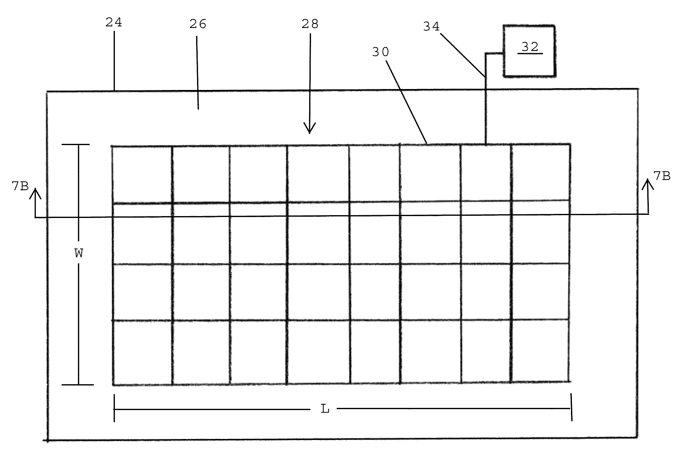
[0047]Referring to FIG. 7A, in one embodiment, the top surface 26 of the mattress 24 preferably includes a central area 28 having a length L and a width W. The central area 28 is preferably sized and shaped to accommodate a wide variety of patients having various heights, weights and widths. In one embodiment, the central area 28 of the top surface 26 is sized, shaped and configured to accommodate virtually any patient that may be placed atop the mattress 24.

[0048]In one embodiment, the top surface 26 of the mattress 24 is covered by a plurality of sensors / actuators 30 that extend over the central area 28. Each of the sensors / actuators 30 is in communication with a system controller 32 via one or more communication line...


PUM


Abstract

A pressure sore relief system includes a plurality of sensors in communication with a surface, whereby each sensor operates independently of one another for detecting a pressure level at a particular region of the surface and generating a feedback signal that corresponds to the detected pressure level, and a system controller adapted to receive the feedback signals from the sensors and generate a plurality of output signals in response to each of the feedback signals. The pressure sore relief system includes a plurality of actuators in communication with the surface and being adapted to receive the output signals from the system controller, whereby each output signal generated by the system controller is associated with one of the actuators. The actuators are adapted to selectively vibrate for minimizing the likelihood of a patient developing pressure sores. The pressure sore relief system may be positioned over a mattress or a chair.

Description

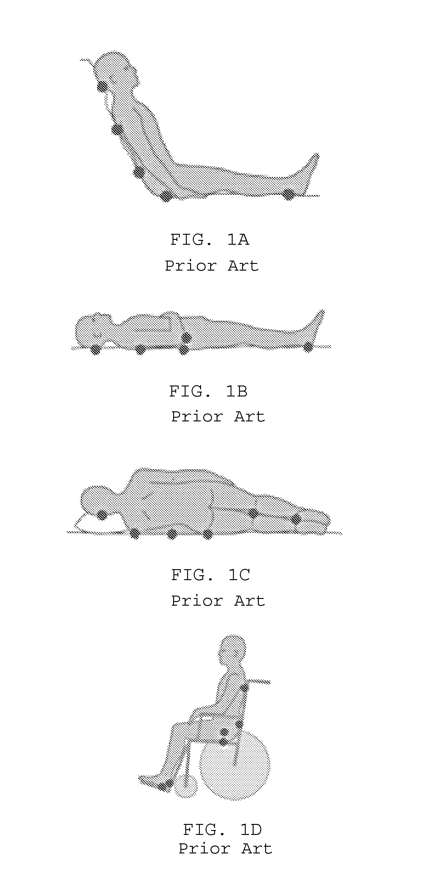
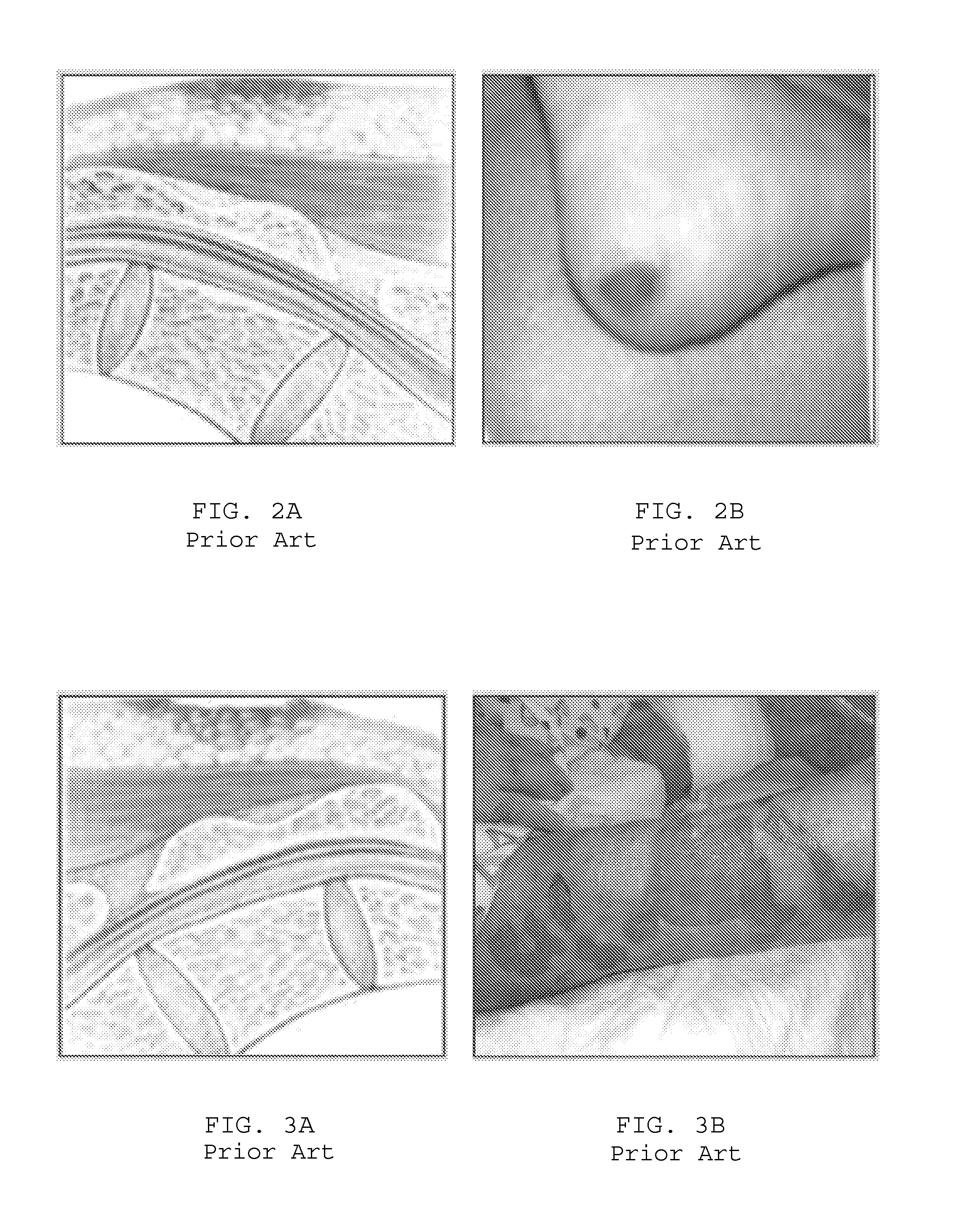
BACKGROUND OF THE INVENTION[0001]1. Field of the Invention[0002]The present invention generally relates to medical devices, and more so specifically relates to medical devices, systems and methods for relieving pressure sores.[0003]2. Description of the Related Art[0004]Pressure sores result when body parts, such as heels, ankles, tailbones, buttocks, or hips, rub against surfaces such as mattresses, bed sheets, and wheel chairs. Pressure sores are not only very painful, but they are also prone to infection, which can spread to the bones and blood stream.[0005]FIGS. 1A-1D show the different points where pressure sores may occur when patients are supported in different positions. The spots on the patient shown in FIGS. 1A-1D indicate where the pressure sores are most likely to occur.[0006]There are four different stages of pressure sores, with stage I being the mildest and stage IV being the worst. Referring to FIGS. 2A and 2B, in stage I, the skin is intact with non-blanchable redne...

Claims


Application Information

Patent Timeline
Patent Type & Authority Patents(United States)
IPC IPC(8): A47B71/00
CPCA61B5/447A61B5/6891A61B5/6894A61G7/057A61H23/0254A61B2562/0247A61G5/00A61G2203/34A61H2201/1604A61H2201/1623A61H2201/1628A61H2201/1633A61H2201/1635A61H2201/164A61H2201/5002A61H2201/5071A61H2201/5092A61H2203/0425A61H2203/0443A61H2205/06A61H2205/081A61H2205/10A61H2205/12
Inventor TURO, ANTHONY MICHAELCHURCHMAN, KAITLYN BETHGARRERA, MATTHEW JOHNNEGRI, BRANDON ANDREW
Owner TURO ANTHONY MICHAEL
Learn More