Technique and device for laminar osteotomy and laminoplasty

a technology of laminar osteotomy and laminoplasty, applied in the field of minimally invasive surgery, can solve the problems of extensive recovery time for patients, back and leg pain, spinal instability,

Inactive Publication Date: 2013-09-10
THE ADELMAN RES
View PDF11 Cites 2 Cited by
  • Summary
  • Abstract
  • Description
  • Claims
  • Application Information

AI Technical Summary

Benefits of technology

[0015]Uniquely, when this procedure is used in conjunction with CT or MRI guidance, it allows for identifying and measuring the relevant anatomy in three dimensions, including the laminar bone distance from the skin, the thickness and depth of the lamina, height of the vertebral arch, the area of the spinal canal, and the angle of advancement and location of the skin incision for the entry point. Further, it also allows for identification of anatomical structures at risk for injury during the procedure and assessment of the relative safety of the procedure being performed.
[0017]In another aspect of the present invention, a device is introduced which protects a patient's sublaminar thecal sac and pari-laminar soft tissue structures while procedures on the spinal lamina of the patient are performed. The device is placed parallel to the longitudinal axis of the lamina and proximate to the lamina. The device has a sub-laminar wall and a supra-laminar wall having curved or angled leading tips to allow the patient's lamina to be separated from the overlaying and underlying tissues. The supra- and sub-laminar walls are part of a cannulate cylinder allowing access to the lamina with surgical tools or a placement of devices, medications, or other therapeutic agents.

Problems solved by technology

Spinal stenosis results in back and leg pain due to the compression of spinal nerves.
Removal of a significant part or the entire facet joints will result in spinal instability.
Traditionally, laminectomies and laminoplasties are open surgical procedures resulting in extensive recovery times for patients and increased costs and risks of complications.
Known techniques and instruments, however, do not provide a method to ensure accurate and safe dividing of the lamina while minimizing the risk of damaging any neuronal elements.
In particular, the methods described by Anderson are only suitable for use in the lumbar spine, where there is little or no risk of damage to the spinal cord or vertebral artery as is the case in the cervical or thoracic spine

Method used


Image

  • Technique and device for laminar osteotomy and laminoplasty
  • Technique and device for laminar osteotomy and laminoplasty
  • Technique and device for laminar osteotomy and laminoplasty

Examples


Embodiment Construction

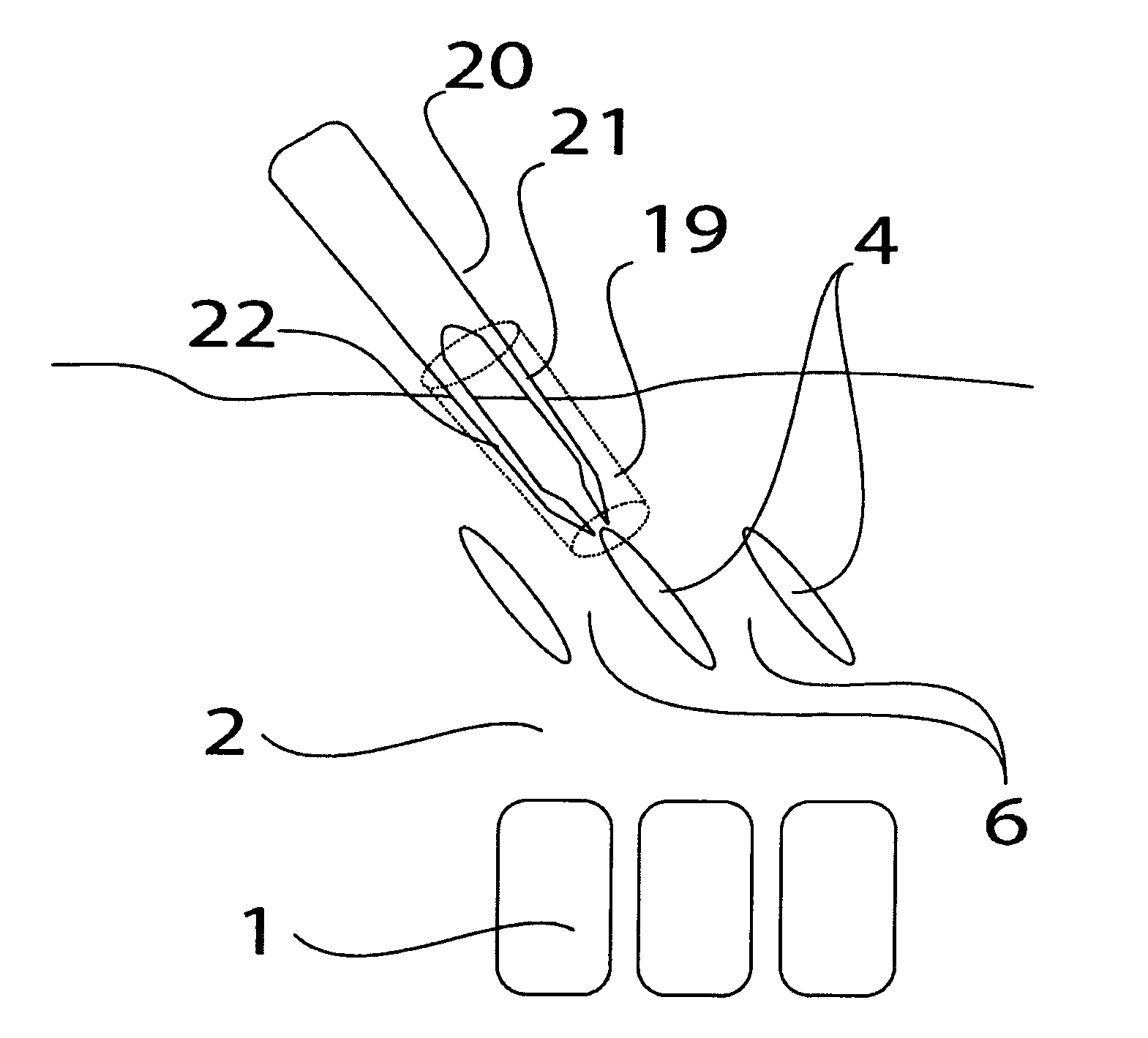
[0041]Preferred embodiments, methods and aspects of surgical implantable devices to be used in dividing of the spinal lamina and elevation of the posterior wall of the spinal central canal are described in this section. This reshaping of the lamina, or laminoplasty results in the creation of more space for the neuronal elements in the spinal central canal. This method is of particular benefit since it can be performed through a small incision under CT, MRI, or other image guidance. Furthermore, the technique can be applied to the cervical, thoracic, and lumbar levels of the spine of any vertebrate.

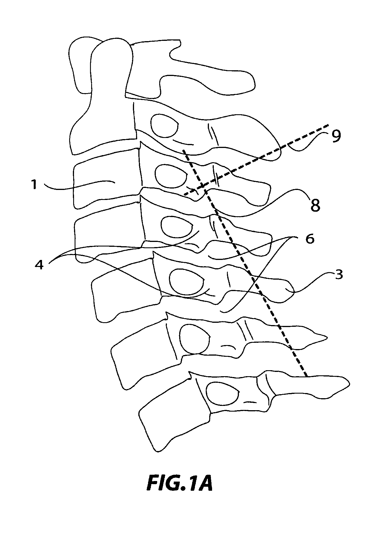
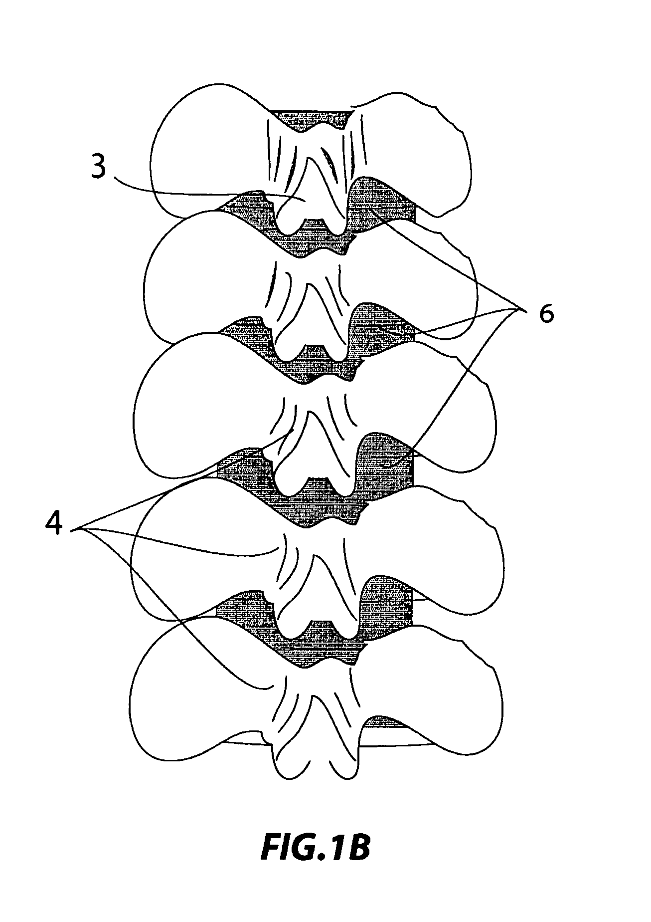
[0042]FIGS. 1-2 show lateral, posterior, and axial views of cervical and lumbar vertebrae respectively. Thoracic vertebra are not drawn as they are similar in the anatomical region relevant to this description. The vertebral bodies 1 create the anterior wall of the central canal 2. The spinous process 3 is a midline bony prominence where the lamina 4 meet. This process elevates the divided...


PUM


Abstract

This invention relates to a technique for performing laminar osteotomy (dividing of the spinal lamina, a posterior structure of vertebra). The term osteotomy is derived from os (bone), tomy (to cut or remove), and laminoplasty (the reshaping of the lamina). This technique can be performed with or without visual assistance such as cameras used with endoscopy, or image guidance such as fluoroscopy, computer tomography (CT) or magnetic resonance imaging (MRI).

Description

CROSS-REFERENCE TO RELATED APPLICATION[0001]This application is a U.S. national phase of PCT Appln. No. PCT / IB2007 / 004560 filed Dec. 14, 2007, which claims the benefit of U.S. Provisional Application Ser. No. 60 / 874,970 filed Dec. 15, 2006 and U.S. Provisional Application Ser. No. 60 / 963,310 filed Aug. 3, 2007, each of which applications are expressly incorporated herein by reference in their entirety.BACKGROUND OF THE INVENTION[0002]1. Field of the Invention[0003]The invention relates to a minimally invasive surgery (MIS) technique and devices for performing laminar osteotomy and laminoplasty; with or without visual or image assistance such as cameras used with endoscopy, fluoroscopy, CT, or MRI.[0004]2. Related Art[0005]Spinal stenosis is a condition characterized by a narrowing of the central spinal canal or inter vertebral foramen. Spinal stenosis results in back and leg pain due to the compression of spinal nerves. Severe cases of spinal stenosis require spinal decompressive la...

Claims


Application Information

Patent Timeline
Patent Type & Authority Patents(United States)
IPC IPC(8): A61B17/70
CPCA61B17/3421A61B17/7071A61B17/8866A61B17/1732A61B17/3472A61B17/8805A61B17/1757A61B2017/3454A61B2019/303A61B2019/306A61B2019/481A61B2019/5483A61B2017/3405A61B2090/3983A61B2090/033A61B2090/036A61B2090/08021A61B17/68A61B17/70A61B17/88
Inventor MEHDIZADE, AMIR
Owner THE ADELMAN RES
Why Eureka
Try Eureka