
Contour extraction device and program

a contour extraction and program technology, applied in image analysis, image enhancement, instruments, etc., can solve problems such as difficulty in recreating the shape of objects, and achieve the effects of preventing excessive calculation cost, simple configuration, and precise contour extraction

Inactive Publication Date: 2013-09-10
KONICA MINOLTA MEDICAL & GRAPHICS INC
View PDF9 Cites 2 Cited by
  • Summary
  • Abstract
  • Description
  • Claims
  • Application Information

AI Technical Summary

Benefits of technology

The patent text describes a device and program for extracting contours from images. The device uses an energy function to determine the accuracy of the contour extraction, and an auxiliary function to indicate the cost of computation. The device analyzes the transition of the energy function and the auxiliary function during the iterative computation to determine the optimal time to stop the computation. This allows for better balance between accuracy and computation cost. The device also uses a simple judging function that is formed by a linear combination of the energy function and the auxiliary function. This function has a local minimum that serves as an endpoint of the computation. The device can also use a point in time when the energy function is smaller than the auxiliary function as the endpoint. This configuration prevents computation cost from increasing too much even if the energy function does not decrease too much. Overall, this device improves the accuracy and efficiency of contour extraction.

Problems solved by technology

However, if the energy function E is defined by the external energy term Ee only, the extracted contour faithfully reproduces noise or the like appearing in an image as well, which makes it difficult to recognize the shape of an object.

Method used


Image

  • Contour extraction device and program
  • Contour extraction device and program
  • Contour extraction device and program

Examples


first embodiment

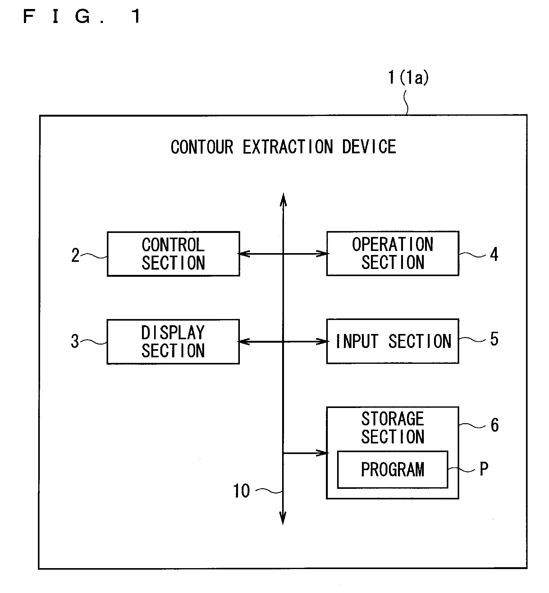
[0043]The hardware configuration of a contour extraction device 1 according to the present invention is described with reference to FIG. 1. FIG. 1 is a block diagram showing the hardware configuration of the contour extraction device 1.

[0044]The contour extraction device 1 extracts a contour of an object appearing on the image data to be processed (hereinafter, referred to as “target image data”) with the use of an active contour model. The contour extraction device 1 is configured as a typical computer and has the configuration in which a control section 2, a display section 3, an operation section 4, an input section 5 and a storage section 6 are connected to a bus line 10.

[0045]The control section 2 is configured as, for example, a CPU and executes a program P stored in the storage section 6 to determine the action of the entire contour extraction device 1, thereby providing a command to the entire contour extraction device 1.

[0046]The display section 3 is configured as a liquid ...

second embodiment

[0086]A contour extraction device 1a according to the present invention is described. The identical components to those described above are denoted by identical reference symbols below, which are not described.

[0087]

[0088]The hardware configuration of the contour extraction device 1a is identical to that of the contour extraction device 1 according to the first embodiment, which is not described (see FIG. 1).

[0089]

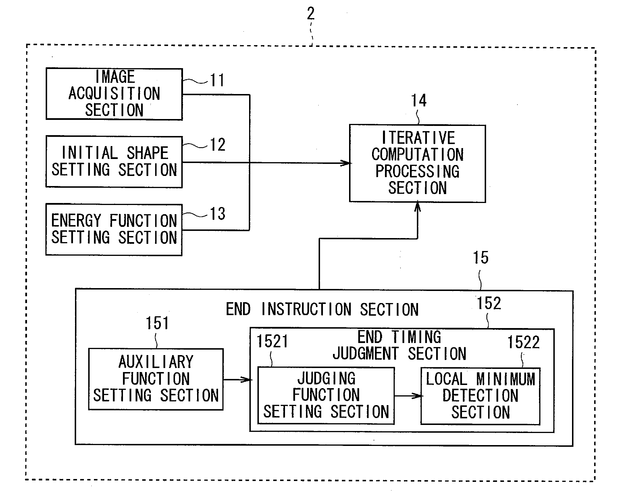
[0090]Similarly to the contour extraction device 1 according to the first embodiment, the contour extraction device 1a has a contour extraction function. The configuration for implementing the contour extraction function is described with reference to FIG. 9. FIG. 9 is a block diagram showing the configuration related to the contour extraction function. In the following description, FIG. 3 and FIG. 4 are referred to as appropriate.

[0091]The contour extraction device 1a includes the above-mentioned image acquisition section 11, initial shape setting section 12, energy funct...


PUM


Abstract

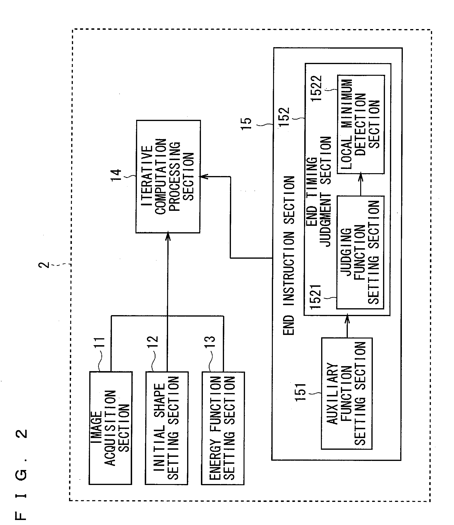
An object of the present invention is to provide the technology capable of appropriately balancing the preciseness of contour extraction and calculation cost. In order to achieve this object, an energy function setting section sets an energy function that is expressed by a weighted linear sum of a plurality of kinds of energy terms defined correspondingly to a state of an active curve and is formulated so as to have a smaller value as approaching a shape of the contour to be extracted, and an iterative computation processing section minimizes the energy function by an iterative computation. An end instruction section sets an auxiliary function formulated so as to monotonously increase in accordance with the number of iteration times of iterative computation and sets a judging function expressed by a linear sum of the auxiliary function and the energy function. Then, a point of time when a local minimum appears in the judging function in the course of the iterative computation is judged as the end timing of iterative computing.

Description

TECHNICAL FIELD[0001]The present invention relates to the technology of extracting a contour of an object included in an image with the use of the active contour model for extracting a contour by convergence of a curve through iterative deformation.BACKGROUND ART[0002]In medical practice, meanwhile, various tests and diagnoses are performed by imaging the affected area within the internal organ, skeleton or the like by means of, for example, ultrasonic waves or X-rays. This enables to visually recognize the information of organs or the like of a body, and it is expected to enhance diagnostic accuracy.[0003]Meanwhile, in recent years, there are growing demands for quantitative or automatic diagnosis aided by a computer, and a computer-aided diagnosis (CAD) system using a computer is studied vigorously. In order to perform CAD using a computer, it is important to precisely extract the information necessary for diagnosis, that is, the region of an organ or the like from the image obtai...

Claims


Application Information

Patent Timeline
Patent Type & Authority Patents(United States)
IPC IPC(8): G06K9/46
CPCG06T7/0083G06T7/0089G06T2207/30101G06T2207/20116G06T2207/10132G06T7/12G06T7/149
Inventor FUJIWARA, KOICHITOYAMA, OSAMU
Owner KONICA MINOLTA MEDICAL & GRAPHICS INC
Learn More