
Vehicle steering control apparatus

a technology of steering control and steering reaction, which is applied in the direction of steering initiation, vessel construction, instruments, etc., can solve the problems of providing the driver an unnatural feeling of achieve the effect of preventing undesired decrease or letdown of the steering reaction

Active Publication Date: 2013-09-10
NISSAN MOTOR CO LTD
View PDF17 Cites 6 Cited by
  • Summary
  • Abstract
  • Description
  • Claims
  • Application Information

AI Technical Summary

Benefits of technology

The patent text is discussing the issue of an unnatural feeling of decrease or letdown of the steering reaction when driving a vehicle due to the actuator producing a torque in the opposite direction opposite to the steering direction at the start of a steering operation. The patent is proposing an apparatus and method to prevent this problem by modifying the control signal to prevent the actuator from producing torque in the opposite direction opposite to the steering direction at the start of a driver's steering operation. The technical effect of this patent is to provide a better steering experience for drivers and to improve the overall performance of the vehicle's steering system.

Problems solved by technology

However, in an operation to set the steering gear ratio to a slow side by rotating the actuator (or a rotating element of the actuator) in the opposite direction opposite to the steering direction of the steering wheel, the actuator tends to produce an actuator torque in the opposite direction opposite to the steering direction at the start of a steering operation, and thereby provide the driver an unnatural feeling of decrease or letdown of the steering reaction.

Method used


Image

  • Vehicle steering control apparatus
  • Vehicle steering control apparatus
  • Vehicle steering control apparatus

Examples


first embodiment

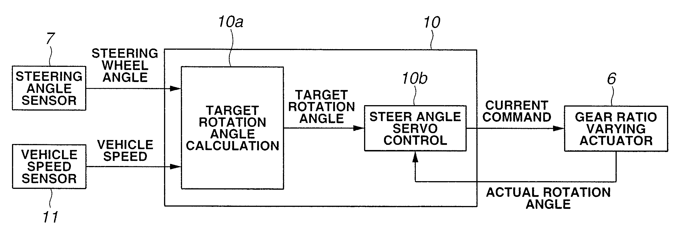
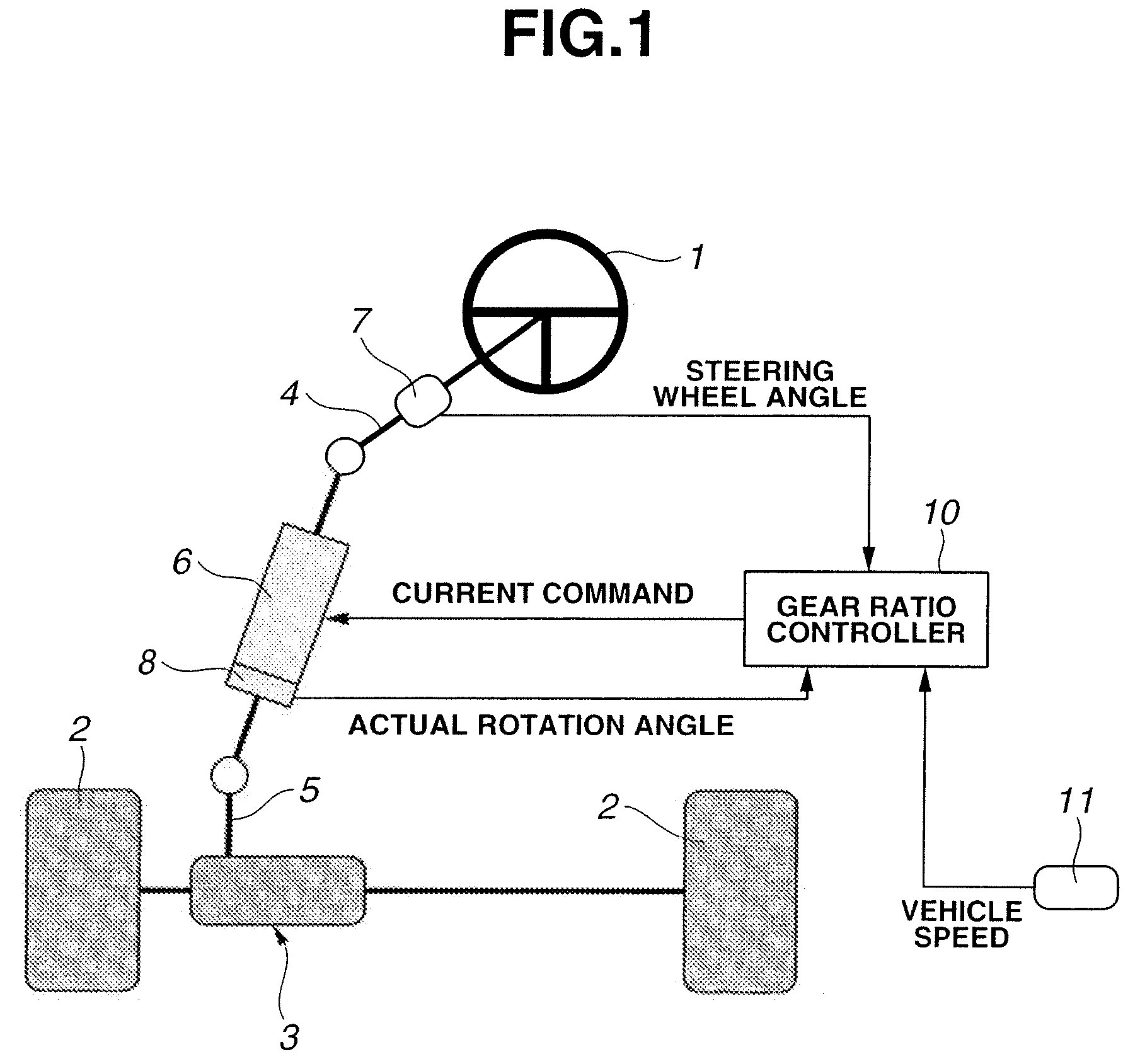
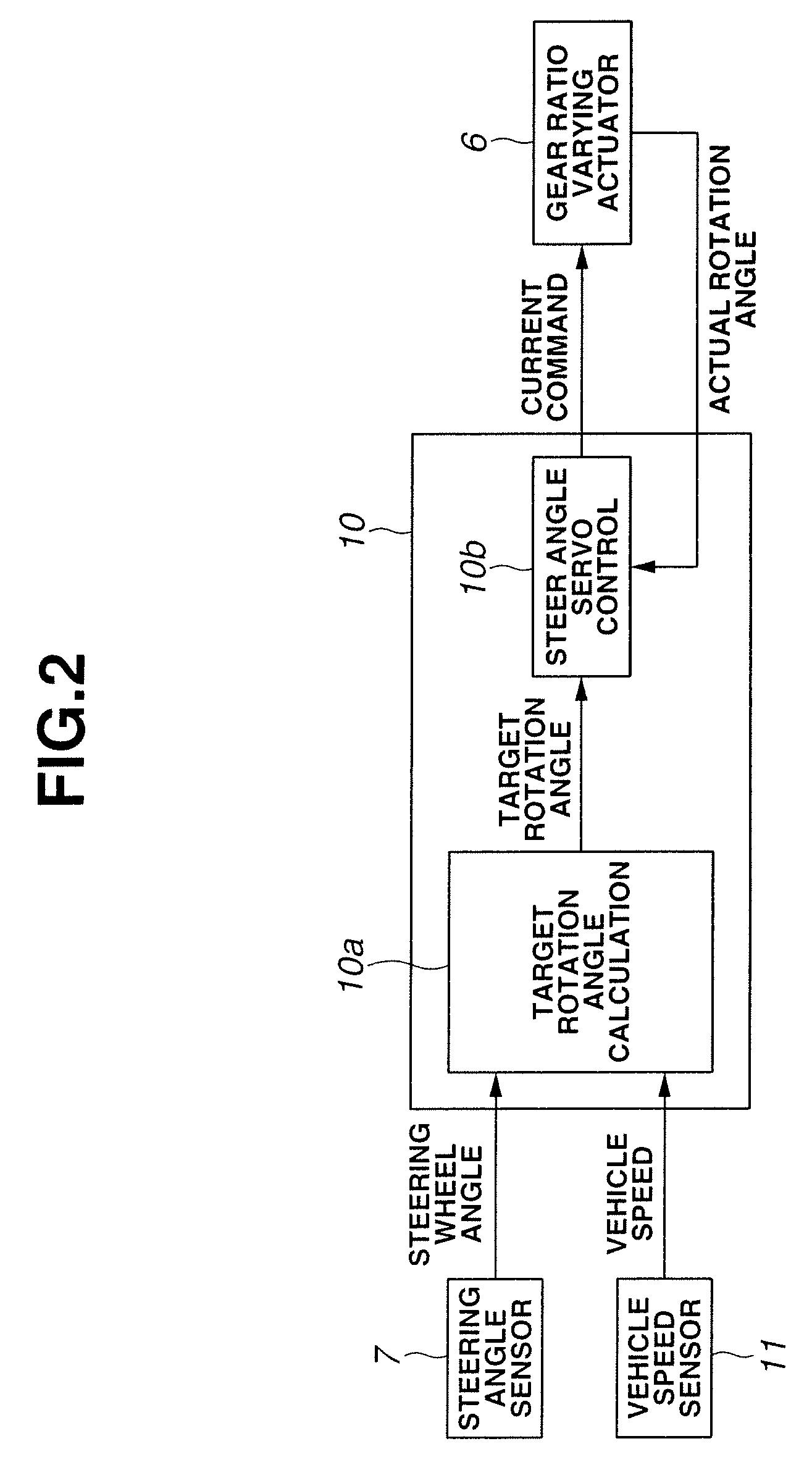
[0018]FIG. 1 schematically shows a vehicle steering control apparatus or system according to the present invention. A vehicle shown in FIG. 1 includes a steering wheel 1, front wheels (steerable wheels) 2 and a steering mechanism 3 which, in this example, includes a rack and pinion type steering gear for steering the front wheels 2. Steering wheel 1 is connected with steering mechanism 3 by a column shaft 4 and a pinion shaft 5. Column shaft 4 and pinion shaft 5 are connected through a gear ratio varying actuator or variable gear ratio actuator (angle inputting actuator) 6. In column shaft 4, there is provided a steering angle sensor 7 for sensing a rotation angle of column shaft 4 (steering wheel angle). Steering angle sensor 7 of this example uses a pulse encoder for sensing the steering angle. Gear ratio varying actuator 6 of this example includes a motor 20 (shown in FIG. 6). A sensor 8 is a motor rotation angle sensor for sensing a motor rotation angle of motor (or angle inputt...

third embodiment

[0086]The thus-constructed steering control system of the third embodiment modifies the value of deviation e of actual rotation angle (θa) from target rotation angle (θh), so as to change the direction of the deviation e toward the steering direction, if the direction of the deviation is opposite to the steering direction, to prevent an actuator torque from being produced in the opposite direction to the steering direction at the start of a steering operation from the steering neutral position, by taking the course of S11→S2→S13→S14→S15→S16. By so doing, the control system can prevent the actuator torque from being produced in the opposite direction to the steering direction, and thereby prevent undesired decrease or letdown of the steering reaction at the initial stage of a steering operation, as shown in FIGS. 12A, 12B, 12C and 12D.

[0087]The third embodiment can provide the following effect in addition to the first, second and third effects (1)˜(3) of the first embodiment. 1

[0088]...


PUM


Abstract

A vehicle steering control apparatus includes an actuator to vary a steering gear ratio of a vehicle wheel steer angle of a steerable wheel to a steering wheel angle. A controller controls the actuator to produce an actuator torque in a steering direction at a start of a driver's steering operation.

Description

BACKGROUND OF THE INVENTION[0001]The present invention relates to vehicle steering control technique (apparatus and / or method) for varying a steering gear ratio of a steering wheel angle to a wheel steer angle of steerable wheel of a vehicle.[0002]A published Japanese patent application, Publication No. JP2005-170129A shows a vehicle steering control system arranged to increase a servo gain of an angle inputting actuator in order to improve a steering stiffness in the vicinity of a steering neutral position where a deviation of an actual rotation angle from a target rotation angle of the actuator becomes smaller.SUMMARY OF THE INVENTION[0003]However, in an operation to set the steering gear ratio to a slow side by rotating the actuator (or a rotating element of the actuator) in the opposite direction opposite to the steering direction of the steering wheel, the actuator tends to produce an actuator torque in the opposite direction opposite to the steering direction at the start of a...

Claims


Application Information

Patent Timeline
Patent Type & Authority Patents(United States)
IPC IPC(8): A01B69/00B62D5/06B60G17/015B62D5/04
CPCB62D5/008
Inventor IGARASHI, KAZUHIROOIDA, TOMOAKI
Owner NISSAN MOTOR CO LTD
Learn More