Camera stabilization device and method of use

a technology for stabilizing devices and cameras, applied in the field of camera stabilization devices and methods of use, can solve problems such as inherently unstable devices, heavy equipment, and inability to work well, and achieve the effects of improving stability, improving stability, and improving stability

Inactive Publication Date: 2013-09-17
CARNEY PETER L
View PDF2 Cites 34 Cited by
  • Summary
  • Abstract
  • Description
  • Claims
  • Application Information

AI Technical Summary

Benefits of technology

[0006]The present invention is a dynamically balanced, light weight multifunctional, camera stabilization device that allows a film or digital video camera to be flown out of arms reach of the operator and still maintain orientation toward the subject matter.
[0007]One embodiment of the present invention or camera stabilization device is a camera stabilizer apparatus consisting of an adjustable camera mounting frame having plurality of at least three weighted counter-balance legs attached. A three-axis rotatable bearing adjustably attached to the camera mounting frame, at the center of inertia of the camera mounting frame and counterweight assembly. A handle attached to the three-axis bearing opposite the camera mounting frame, the handle having an adjustable friction device; allowing the user to pan the camera by rotationally manipulating the handle. A receptacle or socket formed in the end of the handle allowing attachment of the complete apparatus to a jib pole or rod.
[0009]One embodiment of the present invention or camera stabilization device the counter-balance legs having a plurality removably attached weights. In one embodiment, the removable weights are the same mass in another embodiment the removable weights a different mass or the mass of each weight is determined in a graduated series. Each of the plurality of support legs configured to receive a plurality of the weights. The user may choose to install a consistent number of weights on each of the plurality of support legs, however, if the configuration of the camera and camera mounting platform dictate, the user may increase the number of weights on one or more of the plurality of support legs. For example, where a large telescopic lens is installed on the camera, it may be necessary to both, adjust the camera mounting platform, and increase the number of weights on the rear support leg or legs. In one embodiment, the bottom portion of the support legs has a screw thread allowing each individual weight to be threaded or spun unto the support leg. In another embodiment, the support legs having a receiving rod or smooth portion where the individual weights, having a reciprocal hole drilled in the center, can be slid onto the receiving rod and the plurality of weights being securely fastened with a threaded or locking cap which, attaches to the base of the support leg. In yet another embodiment, the plurality of weights friction or interference fit onto the base of the support leg. In yet another embodiment, the counter-balance legs may be extensible in length with a given number of weights to effect a change in balance and / or the location of the moment of inertia. The total number of weights, the length of the counter-balance legs, or the total mass of the weights, added to the camera stabilizer system is dependent upon the mass of the camera mounted onto the system; if a camera is larger, having a substantial mass, additional mass and / or additional length of the legs must be added to allow the moment of inertia of the counter-balance stabilizer to substantially equal the moment of inertia of the camera. If a smaller camera is used, the total mass, the length of the counter-balance legs and / or the total number counter-balance weights can be reduced. In one embodiment of the present invention the density of the counter-balance weights can be modified to allow differential weighting of the support legs without modifying the overall length of the support leg. In yet another embodiment, the support legs have a length adjustment independent of the counter-balance weights.
[0011]In one embodiment of the present invention or camera stabilization device, the counter-balance support legs having an equal length, allowing the user to place the assembled device onto a flat surface, such as a table, and the camera maintaining a substantially level orientation. The user may use the device as a tripod or stationary support during filming or may place the device on a flat surface to allow the use of both hands while making adjustments to the device or to the camera. The user may also use the support legs as handles during filming. The assembled camera stabilization device can be stored while securely resting on the counter-balance legs.

Problems solved by technology

However, these types of devices do not work well when it is necessary to have the camera in motion along with the subject and, this is especially true, when the camera is hand held or supported by a user.
Due to the requirement of high moment of inertia, most camera stabilization devices are heavy and can be unwieldy.
However, these devices are inherently unstable and require the operator to employ both hands to control field of view and stability.
A limitation for each of these devices is that they cannot be extended away for the user or operator.
However, this device does not include any form of stabilization and if combined with any of the other aforementioned devices, the user would not be able to reach up and control at least one axis of the camera in order to direct the shot or completely stabilize the image.

Method used


Image

  • Camera stabilization device and method of use
  • Camera stabilization device and method of use
  • Camera stabilization device and method of use

Examples


Embodiment Construction

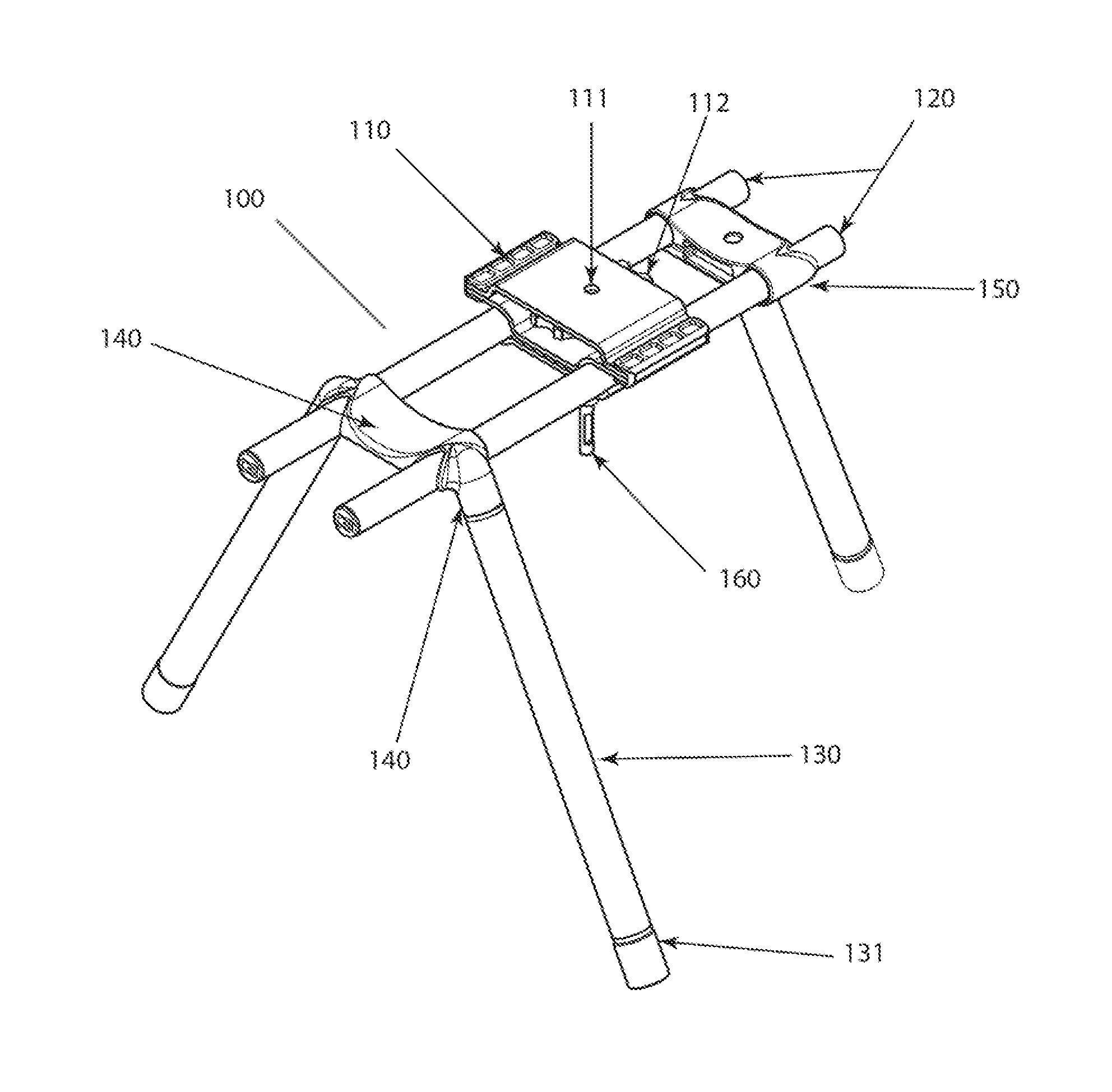
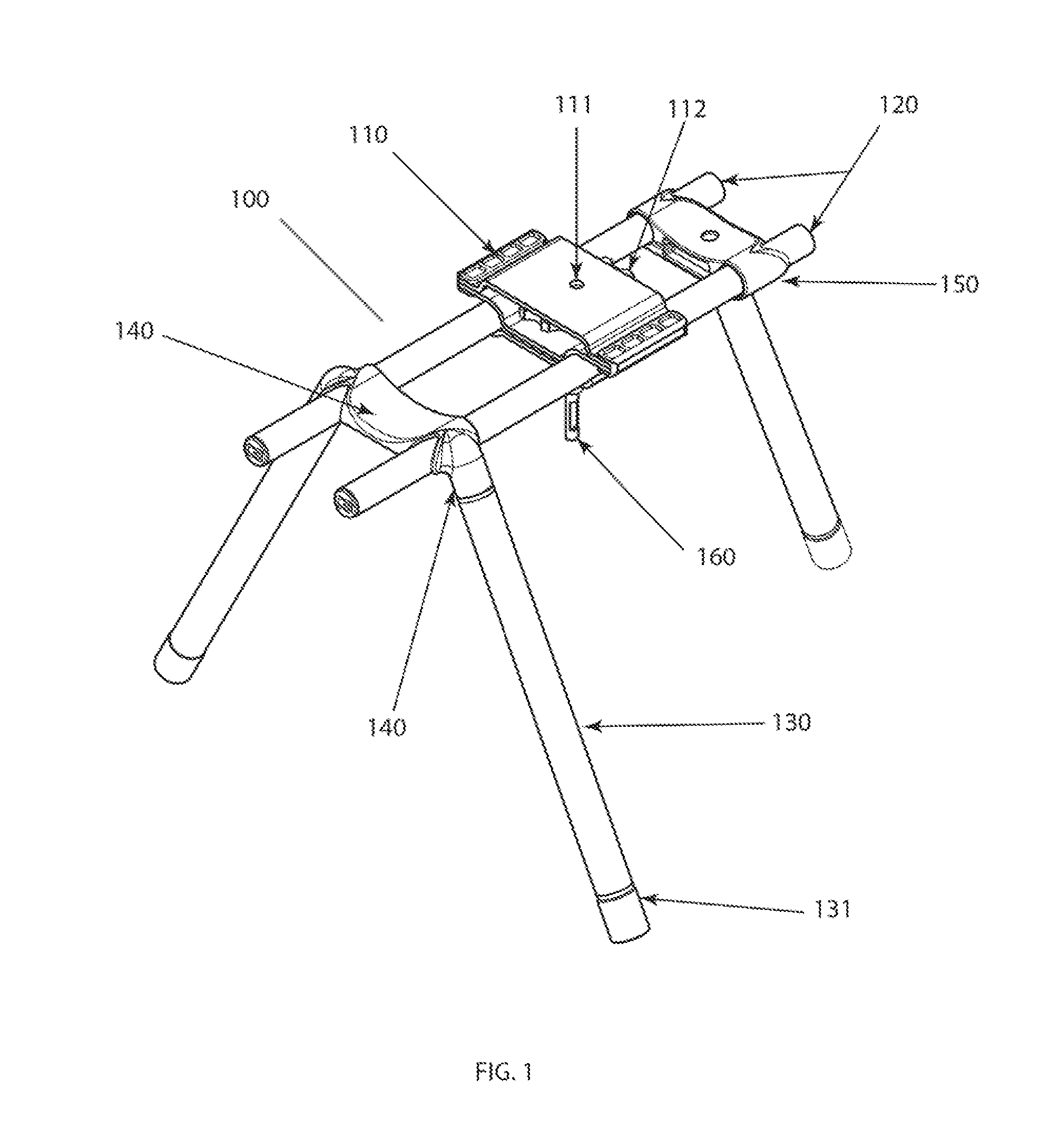
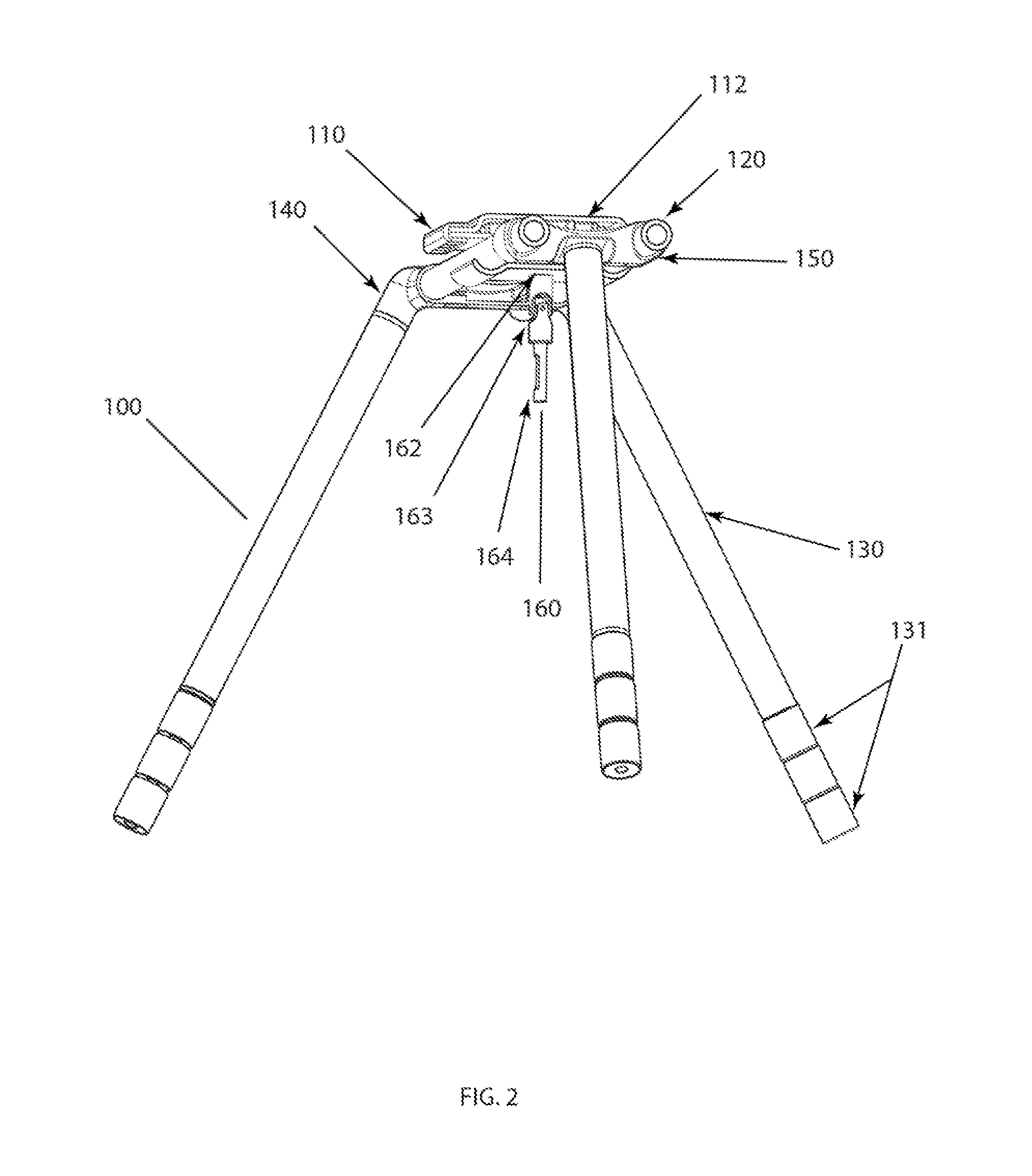
[0034]For the purposes of promoting an understanding of the principles in accordance with the disclosure, reference will be made to the embodiments illustrated in the drawings and specific language will be used to describe the same. It will nevertheless be understood that no limitation of the scope of the disclosure is thereby intended. Any alterations and further modifications of the inventive features illustrated herein, and any additional applications of the principles of the disclosure as illustrated herein, which would normally occur to one skilled in the relevant art and having possession of this disclosure, are to be considered within the scope of the disclosure.

[0035]As used in this specification and the appended claims, the singular forms “a,”“an,” and “the” include plural referents unless the context clearly dictates otherwise. In describing and claiming the present disclosure, the following terminology will be used in accordance with definitions set out below. The term ca...


PUM


Abstract

The present invention is a dynamically balanced, lightweight multifunctional, camera stabilization device that allows a film or digital video camera to be flown out of arms reach of the operator and maintain orientation toward the subject matter, while allowing the operator smooth control of rotation or pan of the camera.

Description

BACKGROUND OF THE INVENTION[0001]A number of devices have been introduced to help film makers produce clear, stabile motion picture, home movies and video images, including, tripods, monopods, clamps, booms, etc. These devices work well when the camera is in a relatively fixed position and the subjects are in motion. However, these types of devices do not work well when it is necessary to have the camera in motion along with the subject and, this is especially true, when the camera is hand held or supported by a user.[0002]There are some devices designed to stabilize a camera when it is hand held or supported by the user that are based on the principle of lowering the center of gravity of the assembly below a three-axis pivot point where the user's handle is attached, and by weighting the assembly to create a high moment of inertia. In this arrangement, the camera is allowed to pivot freely about the center of inertia of the whole filming apparatus, similar to the basic device shown...

Claims


Application Information

Patent Timeline
Patent Type & Authority Patents(United States)
IPC IPC(8): G03B17/48H04N5/225F16M11/04F16M11/02
CPCF16M11/02F16M11/04F16M11/041F16M11/048F16G13/04F16M11/2078G03B17/563F16M2200/022F16M2200/04
Inventor CARNEY, PETER L.
Owner CARNEY PETER L
Why Eureka
Try Eureka